| Last updated on 28-Aug-2001 2:11 PM |  |
 |
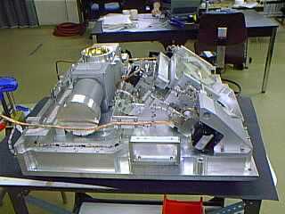
Front Optical Bench
1 Removing the Front Optical Bench
2 Refitting the Front Optical Bench |
|||
|
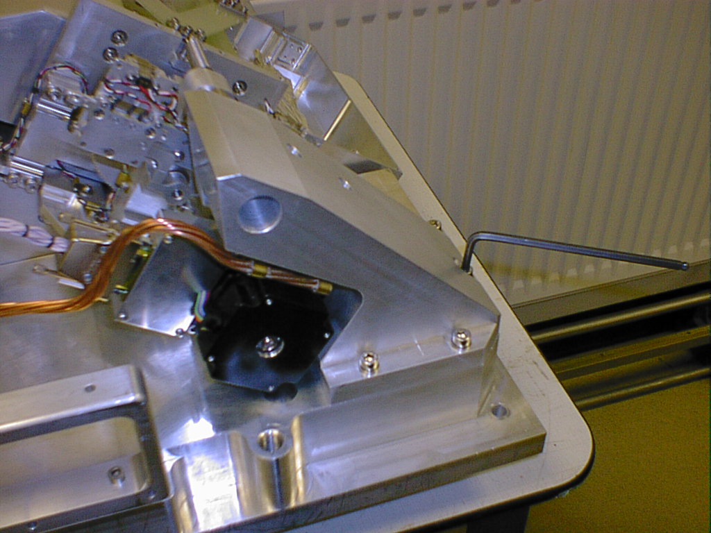
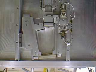
Check that the cryostat is rotated to the correct angle (5 degrees past the vertical) and remove the six M8 bolts with invar spacers from the interface surface of the main optical bench (MOB).
|
|||
|
|
|
||
|
|
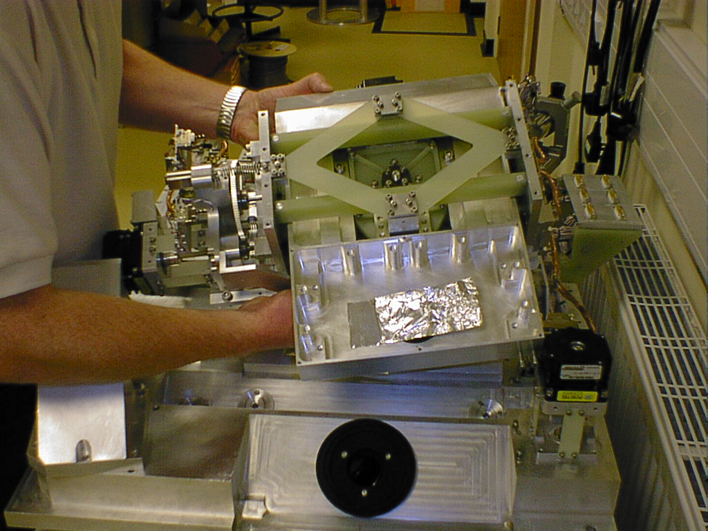
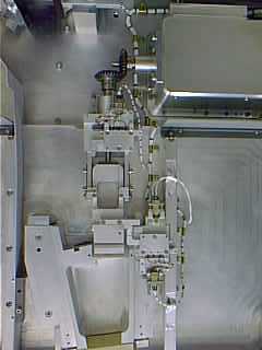
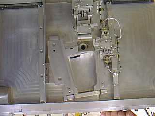
Mounting the Front Optical Bench onto the Main Optical Bench. |
||
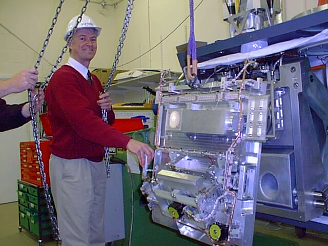
| Position the front optical bench (FOB) on a storage table in front of the cryostat with the filter assembly end facing the MOB, Fit an eyebolt and shackle to the upper-centre of the FOB (if not already there) and attach a single lifting hook from the overhead crane. Carefully lift the filter end of the FOB using the crane whilst two people support Its weight using the handles, the storage table can now be slid from underneath, The two people holding the handles can now gently lower the top end of the FOB so that it is freely supported by the crane (~50kg) ensuring that it does not swing against the cryostat. | |||
|
|
|||
|
With one or two people guiding using the handles, bring the FOB into position in front of the MOB adjusting its height and position as required with the crane.
|
|||
|
|
|
||
| Slowly guide the FOB towards the MOB using the trolley facility on the crane, ensure that the baffle plates on each side interleave properly and that they are not causing obstruction, Check also that the three reference pads are not causing an interference. Once the two interface surfaces have been properly mated together insert and partially tighten the six M8 bolts remembering the invar spacers, three per side. | |||
 |
|||
| Remove the lifting hook and eyebolt from the instrument and rotate the cryostat until the FOB/MOB interface is about 10 degrees off the horizontal with the filter assembly end lowest this will allow the weight of the FOB to push itself into the corner defined by the three reference pads, Slacken the six M8 bolts and check that the FOB is sitting properly against the three reference pads on the MOB this defines its position to the rest of the instrument, once this check has been completed the bolts can be tightened to a torque of 36.2Nm. | |||
|
|
|||
|
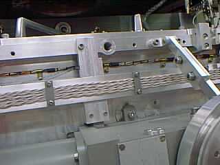
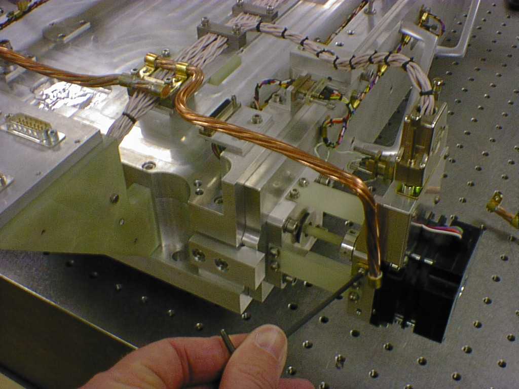
Connect the two twisted copper strand thermal wicks to the filter wheel motors using the screws and washers which should be in place there. |
|||
 |
|||
|
Make sure that the control racks are depowered then connect the six stepper motor cables and the one datum status cable, checking that the labels on each cable corresponds to the engraved identification on each of the connector plates, Refit the long panel cover over the joint between the FOB/MOB interface at the JT side this should also be taped up. |
|||
| Refit the baffle plate along the gap between the FOB and the detector box radiation shield. | |||
3. Removing Focus Translation Mechanism from Front Optical Bench
|
|||
|
3.1. If necessary remove the fore optics (See Fore Optics procedure) This is only required to be done if the focus motor connector cannot be undone by hand. |
|||
|
|
|||
|
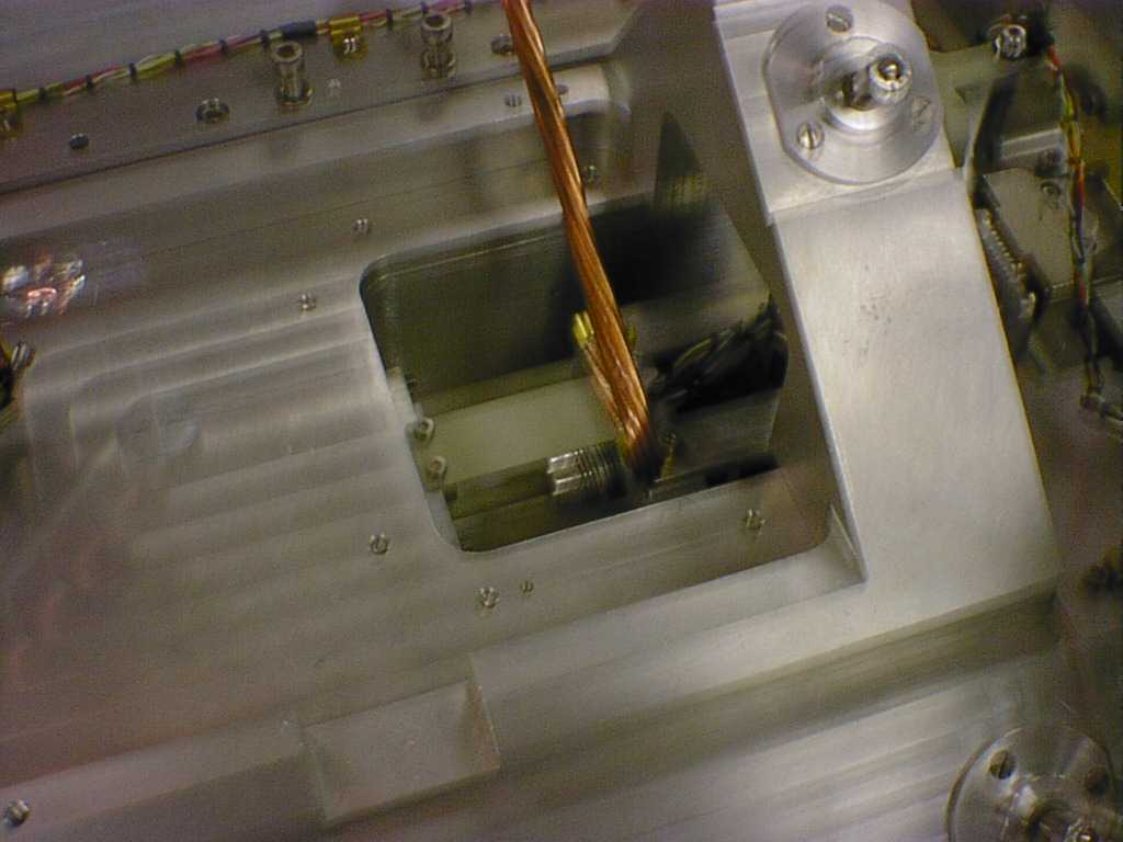
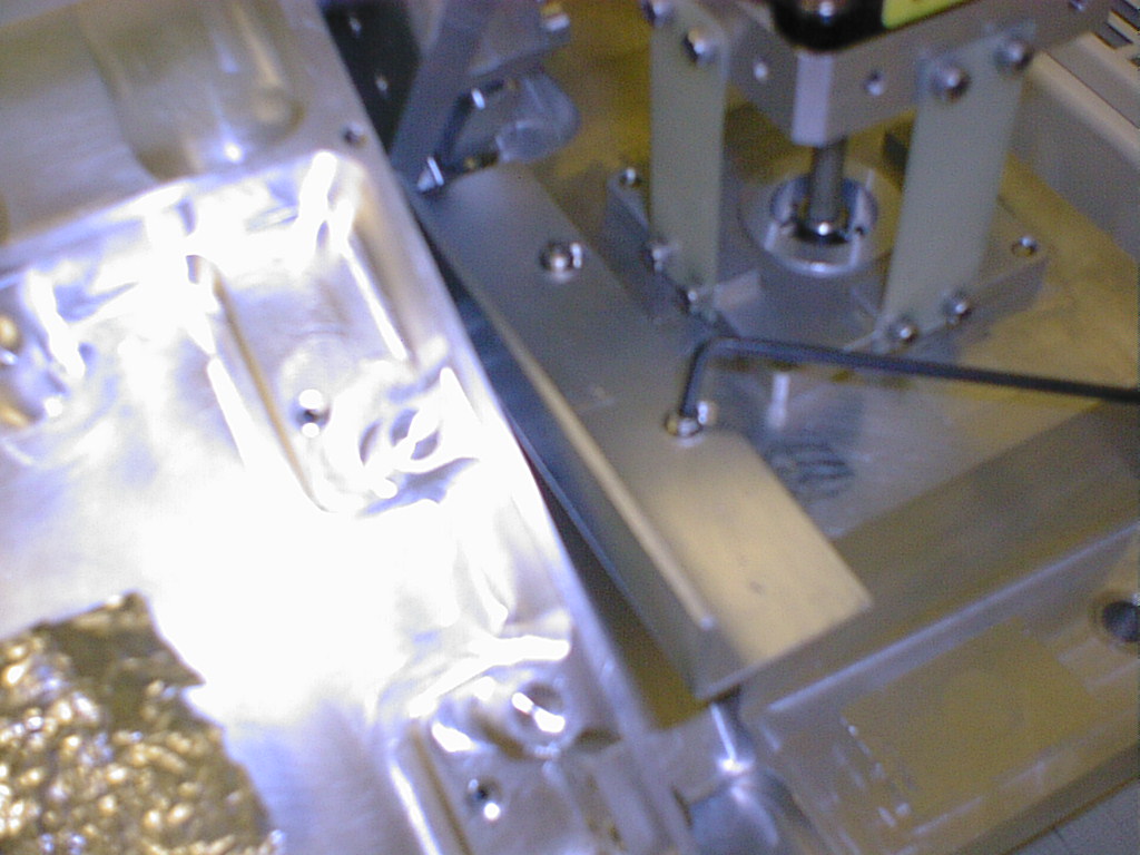
3.4. Access to screws for wick through translation support frame |
|||
|
|
|||
|
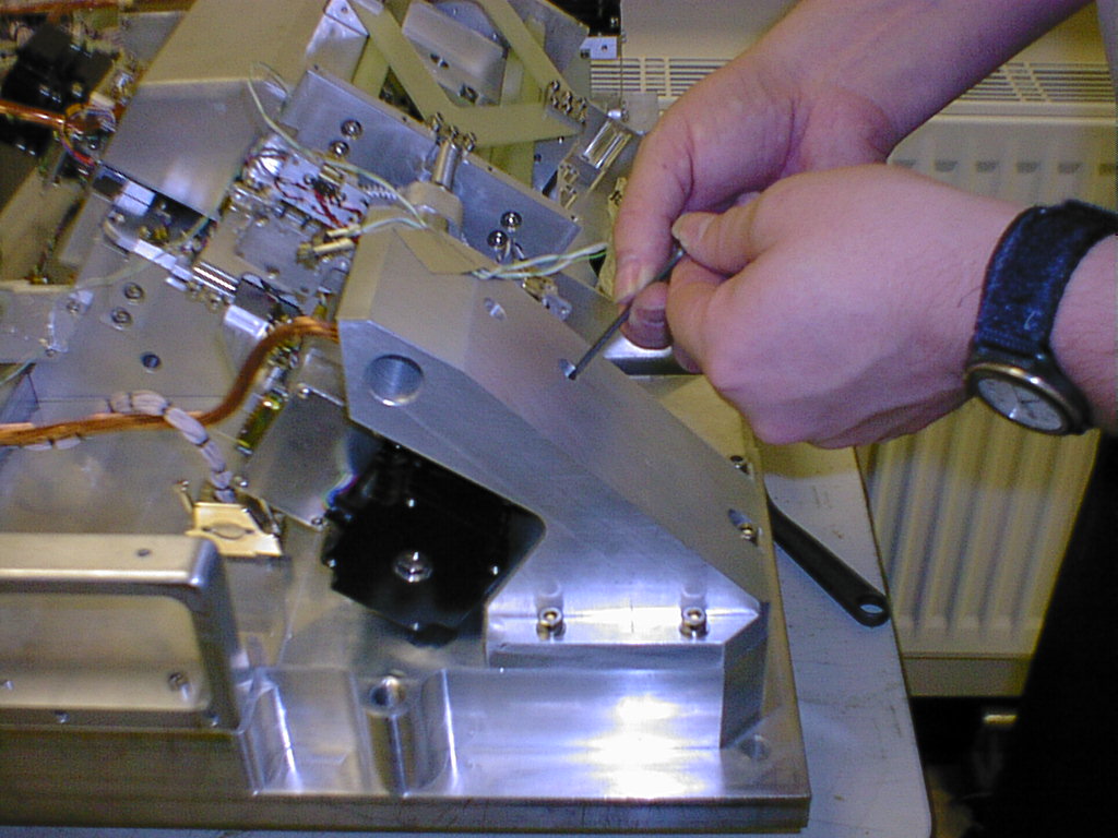
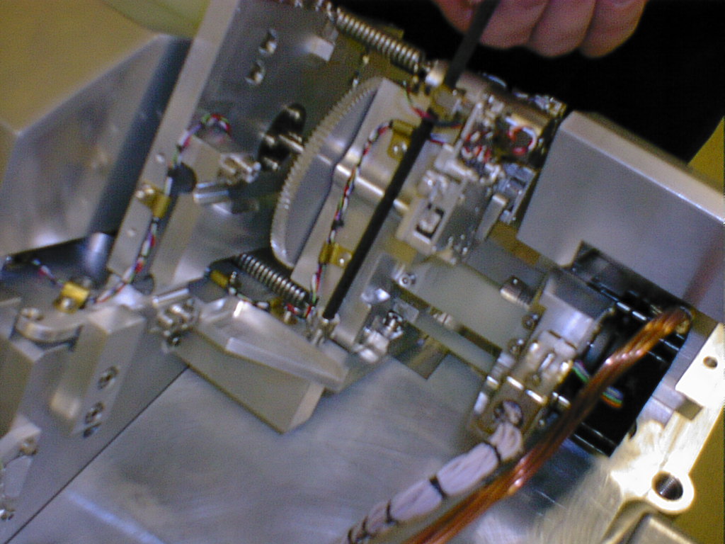
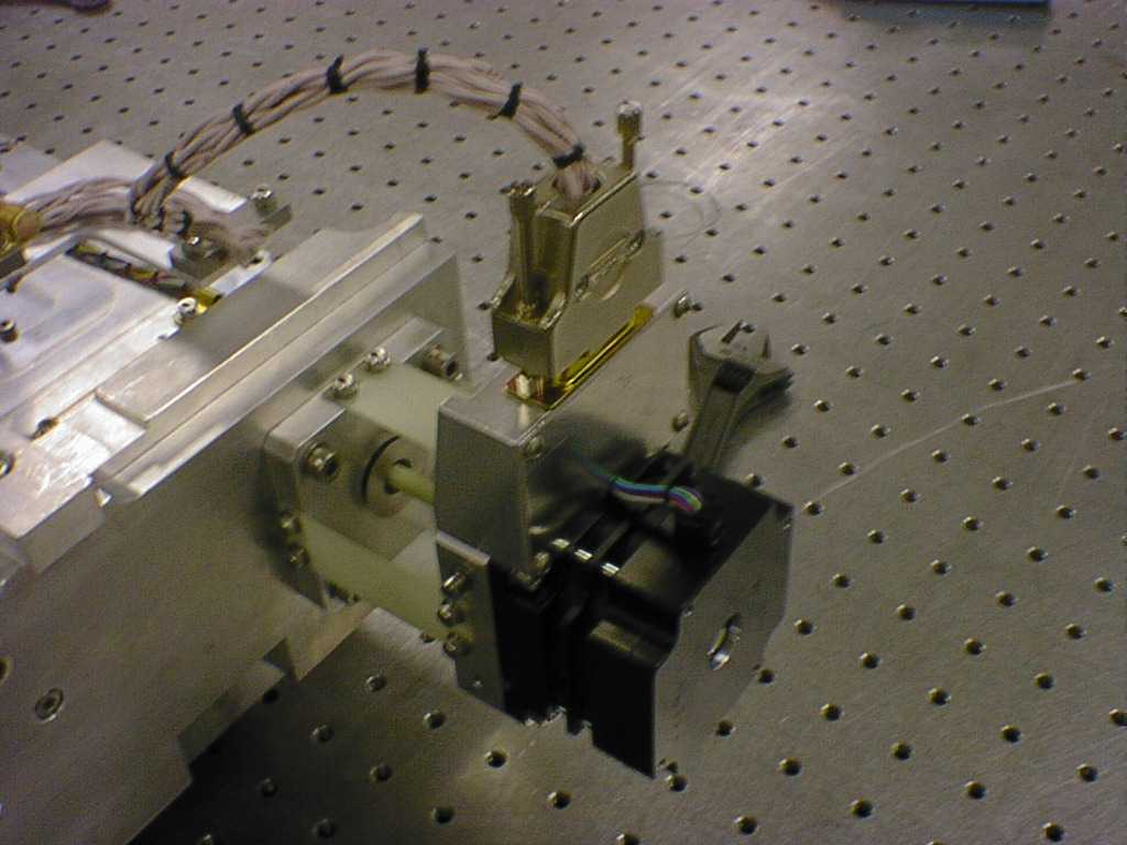
3.6 Undo M8 hex socket head screws through translation support frame. |
|||
|
3.7 Undo 5 M6 hex socket head screws fixing translation support frame to front optical bench and remove. |
|||
|
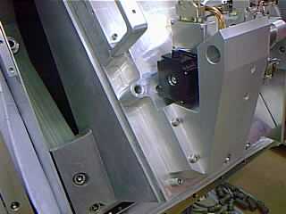
3.8 Remove baffle plate (2 M3 hex socket screws) beside image extract motor to gain access to one of the screws fixing the focus/translation support plate to front optical bench. |
|||
|
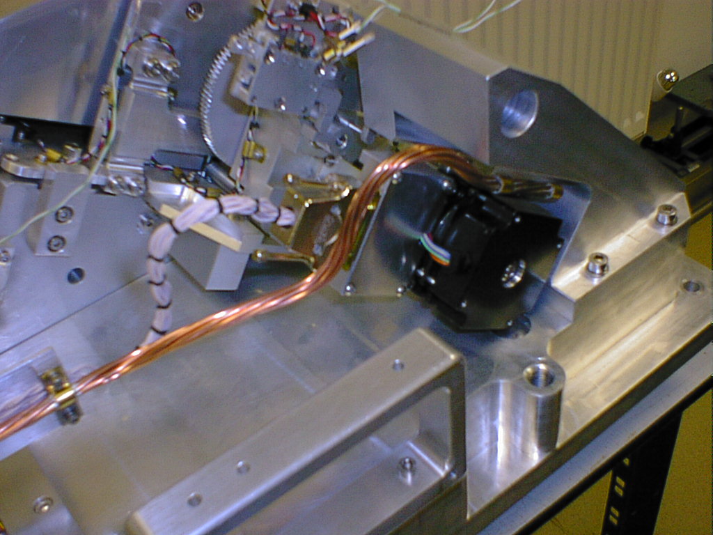
3.9 Support and the weight of the mechanism and undo the six M6 hex socket head screws fixing the focus/translation support plate to the front optical bench wedge. Remember the two screws beside the translation motor.
|
|||
|
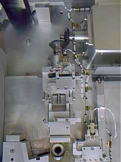
3.10 Carefully remove the focus/translation mechanism from the front optical bench and put down as shown. |
|||
 |
|||
|
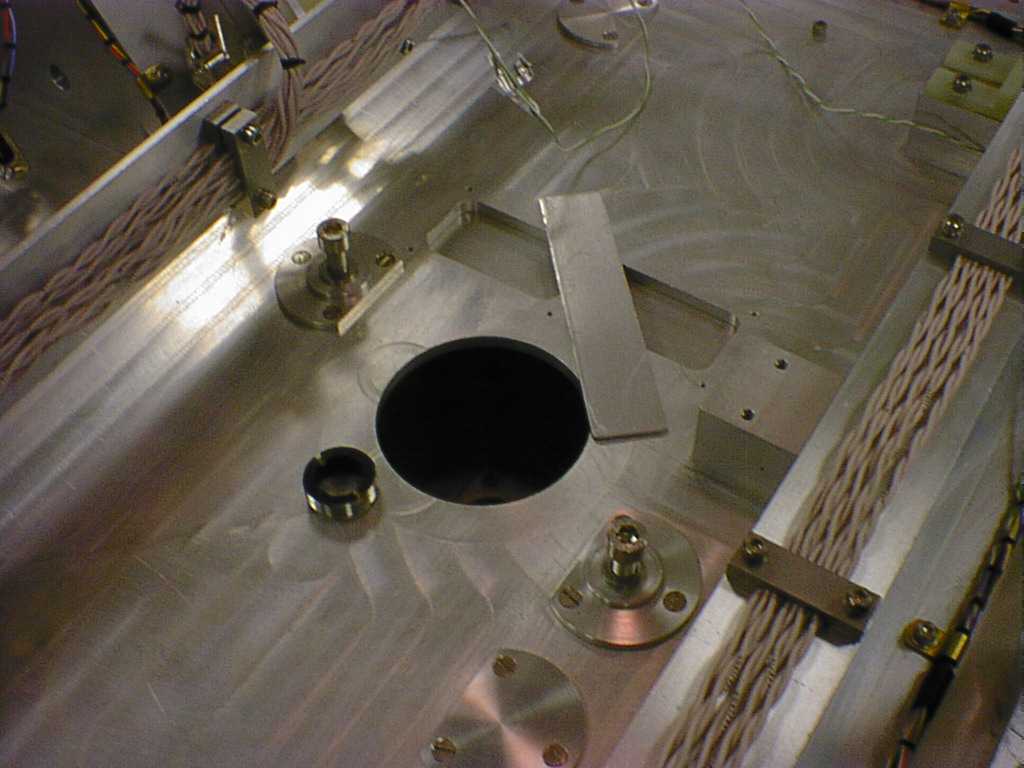
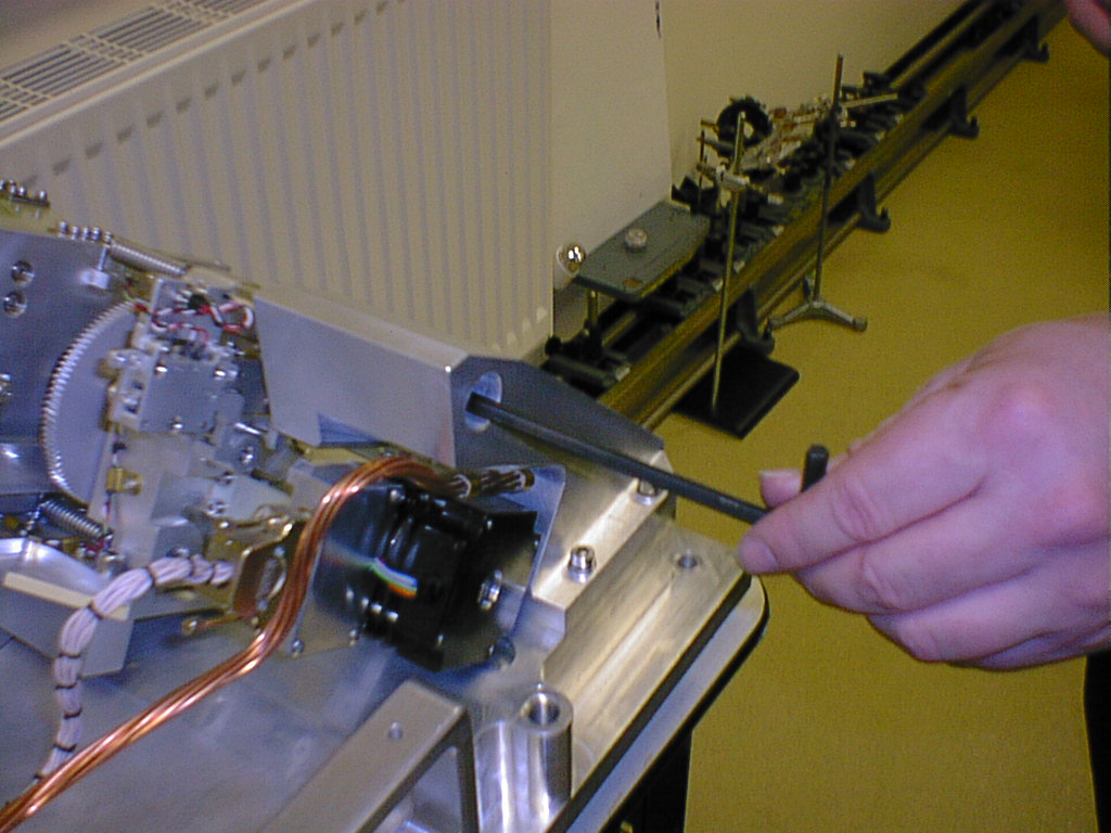
3.11 Check through the blackened detector baffle that the image extract mirror has been retracted. Then cover the aperture (use motor coupling to retract mirror if required). |
|||
|
3.12 To refit the focus/translation mechanism, ensure that the support plate is correctly positioned against the three X and Y defining pads before tightening the six M6 hex socket head screws to a torque of 14.7 Nm. |
|||
|
|
 |
||
|
3.13 Take care when inserting the baffle on the back of the detector box into the baffle on the front optical bench. |
|||
|
3.14. Refit baffle plate as per 3.7 |
|||
|
|
|||
|
3.16. Connect status connector as per 3.4 |
|||
|
3.17. Connect translation connector as wick as per 3.3 |
|||
|
3.18. Connect focus translation motor and wick as per 3.2. |
|||
4 Removing the Filter Assembly |
|||
|
4.1 Position the front optical bench on it's four supporting feet on a flat level surface.
|
|||
|
|
|
||
|
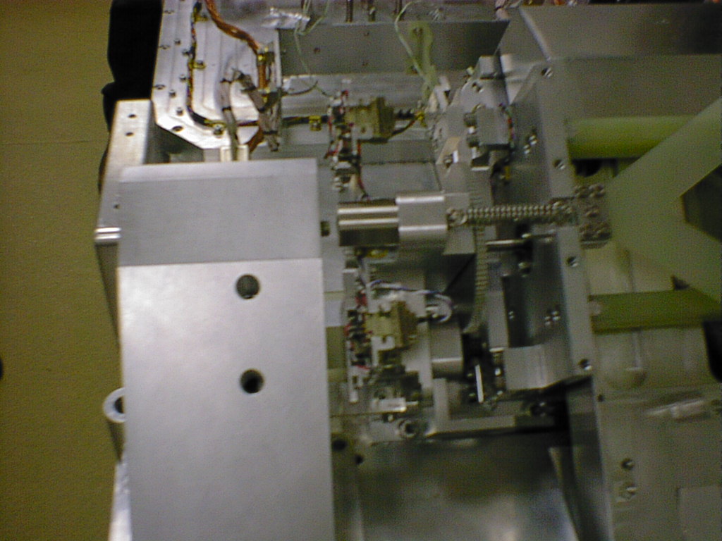
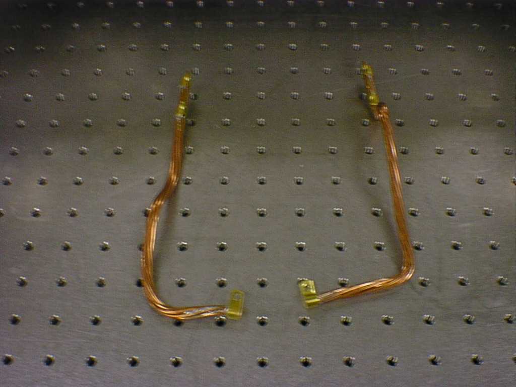
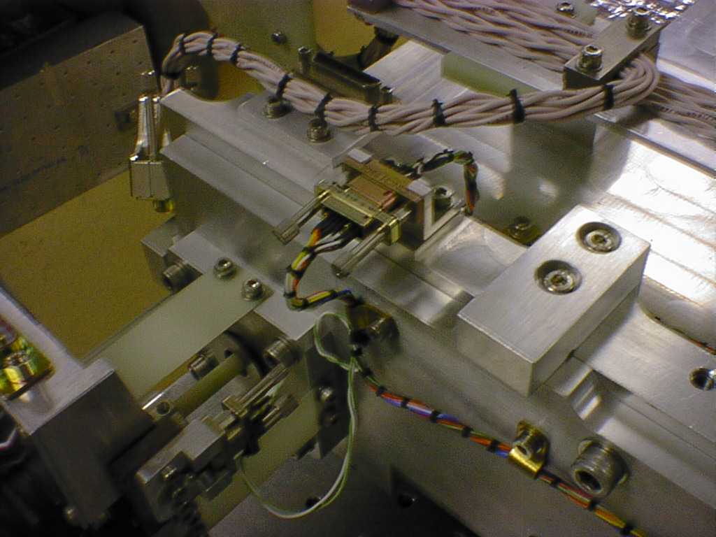
4.2 Completely remove the sections of copper wick which connect both motors to the front optical bench replacing the screws and washers when finished.
|
|||
 |
 |
||
|
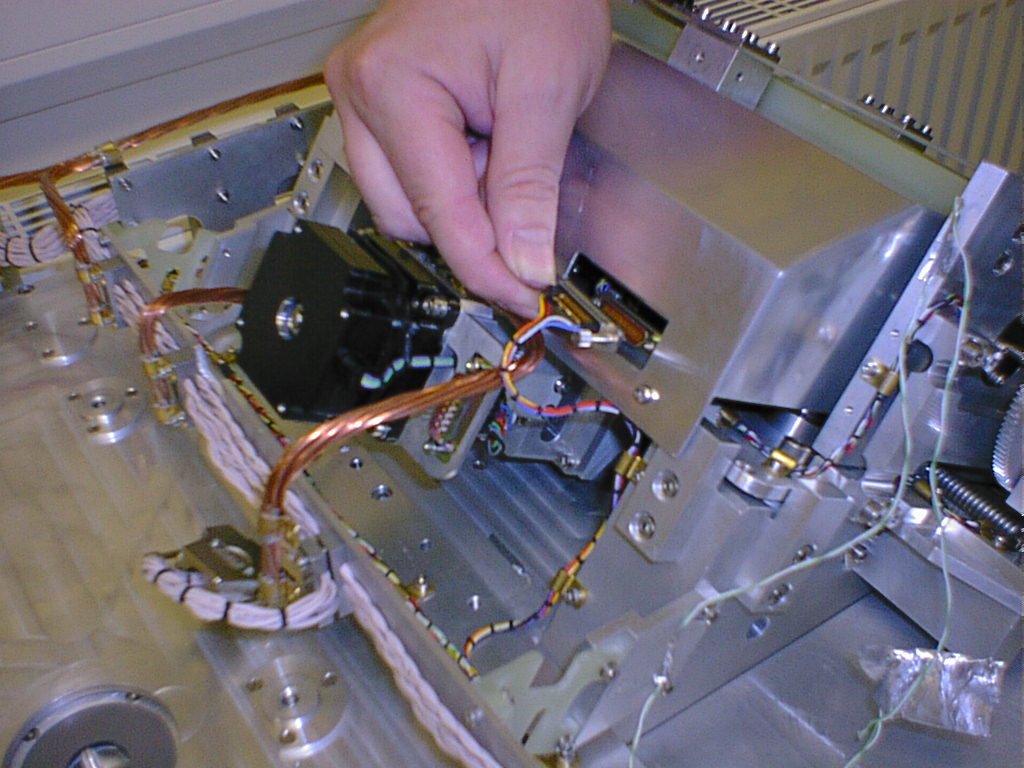
4.3 Disconnect both of the motor connectors and the status connector.
|
|||
 |
 |
||
|
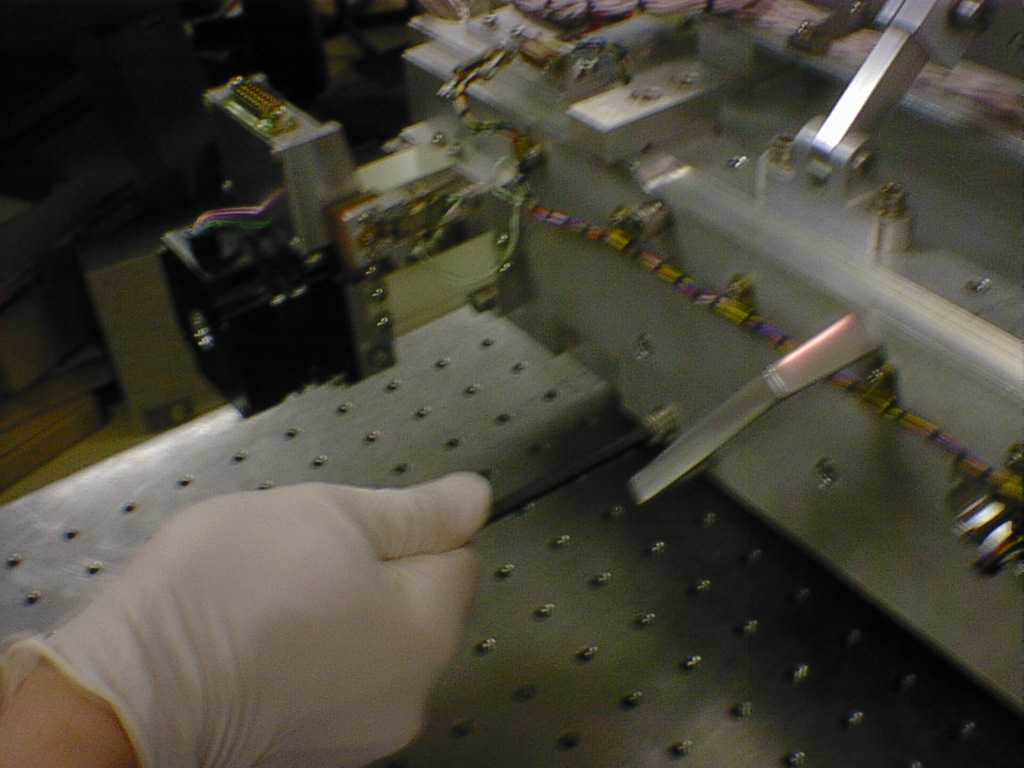
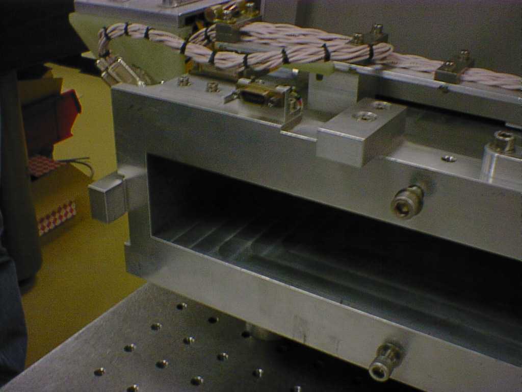
4.4 remove the four M6 screws
on the base plate adjacent to the motors, then using the handles
withdraw the filter assembly carefully from its recess in the bottom
of the front optical bench, once removed replace eh screws in the
front optical bench. Lay the assembly down flat
supported along each side edge with motor connectors facing upwards. Check
through the entrance hole of the filter assembly to see if there
are filters are filters in position, if so manually turn the coupling
on each motor until the blank positions are reached then tape a
cover over the hole on each side.
|
|||
5 Refitting the filter assembly |
|||
|
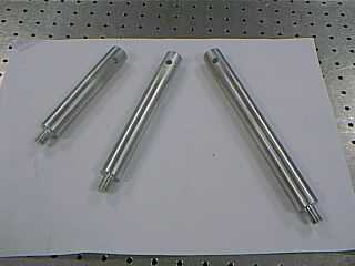
5.1 Fit the three different length extended support feet to the front optical bench at the M12 lifting eye positions. The shortest is fitted in eh central position at the filter end of the front optical bench.
|
|||
|
|
|
||
|
5.2 The longest support is positioned at the opposite
end adjacent to the image extract motor. To fit
this support move the black M12 screw to the vacant hole below the
copper wick then fit the support in the hole previously occupied
by the screw.
|
|||
 |
 |
||
|
5.3 The last support is fitted on the opposite side in the hole adjacent to the translation motor. Two people can now move the front optical bench up on to its side and then turn it over to stand on its three support feet, this gives access to the imager assemblies, care should be taken as there are now exposed mirrors (See Imager Assembly procedure).
|
|||
 |
|||
|
5.4 With the front optical bench positioned this way up, it is possible to slide the filter assembly into its recess in the front optical bench and to locate it properly against eh three defining pads. Secure the filter assembly in position by tightening the four M6 screws to a torque of 14.7 Nm. Reconnect the motor and status connectors and refit the two copper wicks.
|
|||
6 Removing the Imager assemblies from the Front Optical Bench |
|||
 |
|||
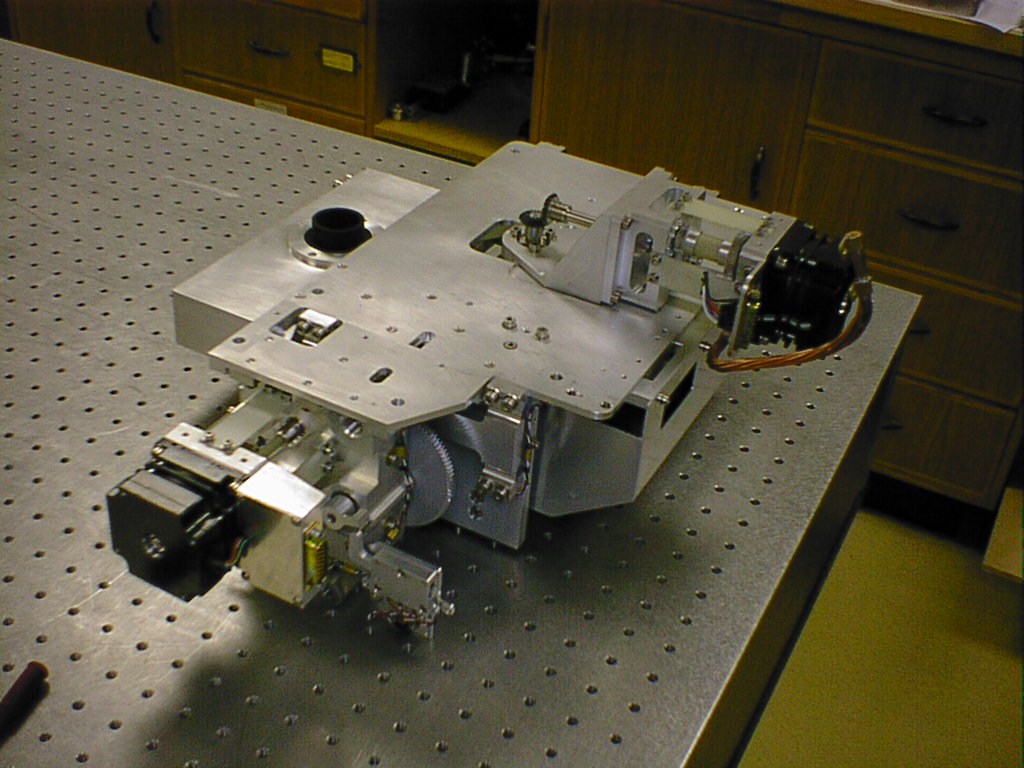
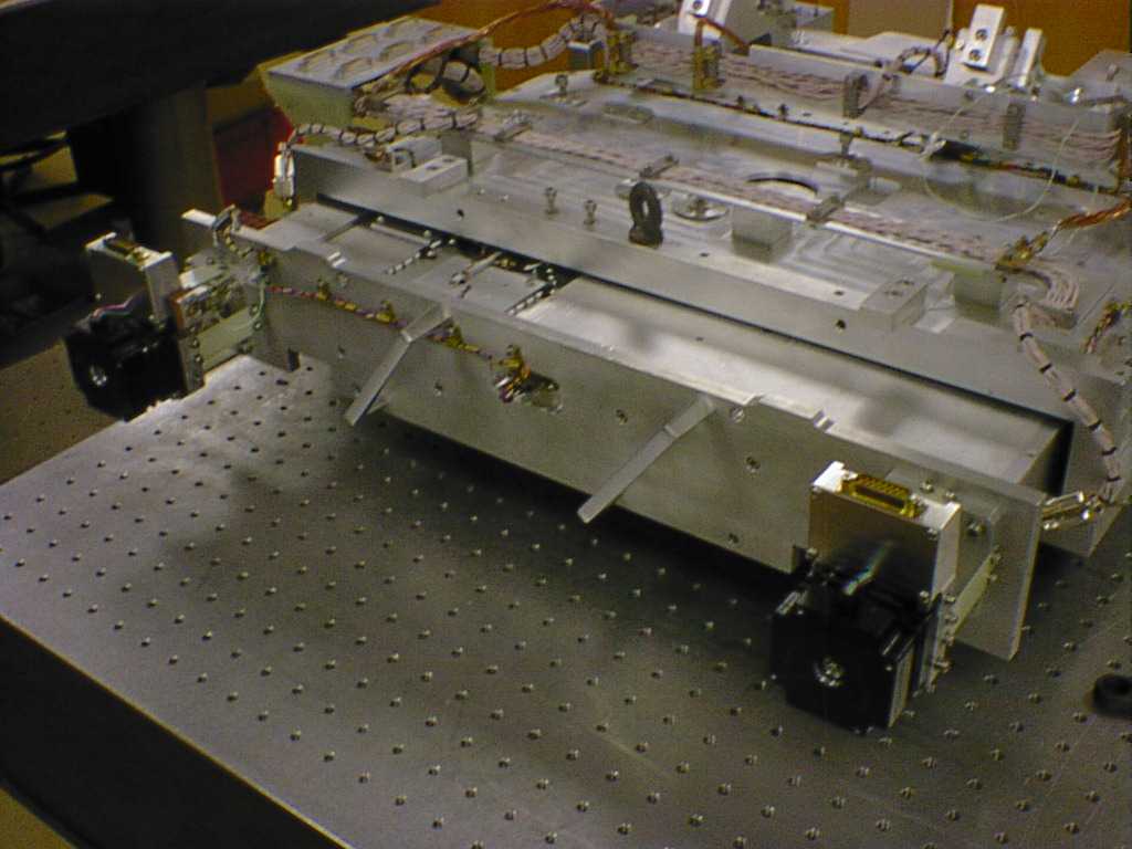
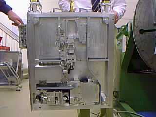
| The Michelle imager consists of four mechanism assemblies
and two optical assemblies, These are all fitted to the side of the
front optical bench (FOB) which interfaces to the main optical bench
(MOB).
In order to get access to the imager assemblies it is necessary to remove the FOB |
|||
|
Once the FOB has been removed it should be positioned on a flat stable surface in one of two ways.
|
|||
| The assemblies can be split into two groups | |||
 |
 |
||
|
|||
 |
 |
||
| Before removing any of the above assemblies ensure that the image extract and inject mirrors have been parked in the spectroscopy position, This can be done manually by turning the coupling on each motor shaft. | |||
 |
 |
||
|
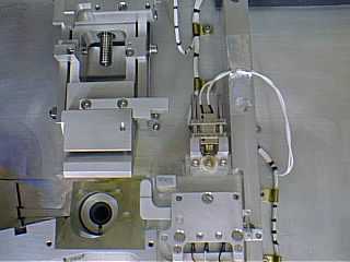
To remove the upper optics housing first disconnect the datum status switch connector and remove the three P-clips attaching the wiring harness to the top of the optics housing replace the screws in the housing for safe keeping. Remove the wiring harness P-clip fixings which are securing the captive grey baffle plate to the FOB. Undo the three M5 socket head screws which are securing the upper housing to the FOB and remove the housing with the baffle plate. This assembly contains the toroid mirror and a small flat mirror and should be stored safely. |
|||
 |
|||
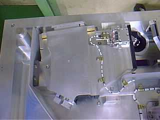
| To remove the lower optics housing disconnect its datum status switch connector and undo the three M5 socket head screws which are securing the lower housing to the FOB, As one of the screws is partially obstructed behind the micro-switch assembly this screw should be undone last as you lift the housing from its mounting. This assembly contains the aspheric mirror and should be stored safely. | |||
 |
|||
| When refitting both optics housings it is important to ensure that they are mounted properly located hard against the machined alignment features provided by the FOB. | |||
 |
|||
| Both the extract and inject mirror assemblies are mounted similarly to the FOB on dowels and secured by four socket head screws at the bevel gear end of the assembly (extract M4 & inject M3). To remove these assemblies disconnect its associated datum switch connector and undo the four fixing screws, remove the P-clip fixing from the extract mirror assembly, Lift the assemblies squarely until they are free from the dowels turning the gears as necessary. These assemblies have flat mirrors mounted to them and should be stored safely. | |||
|
|
|||
|
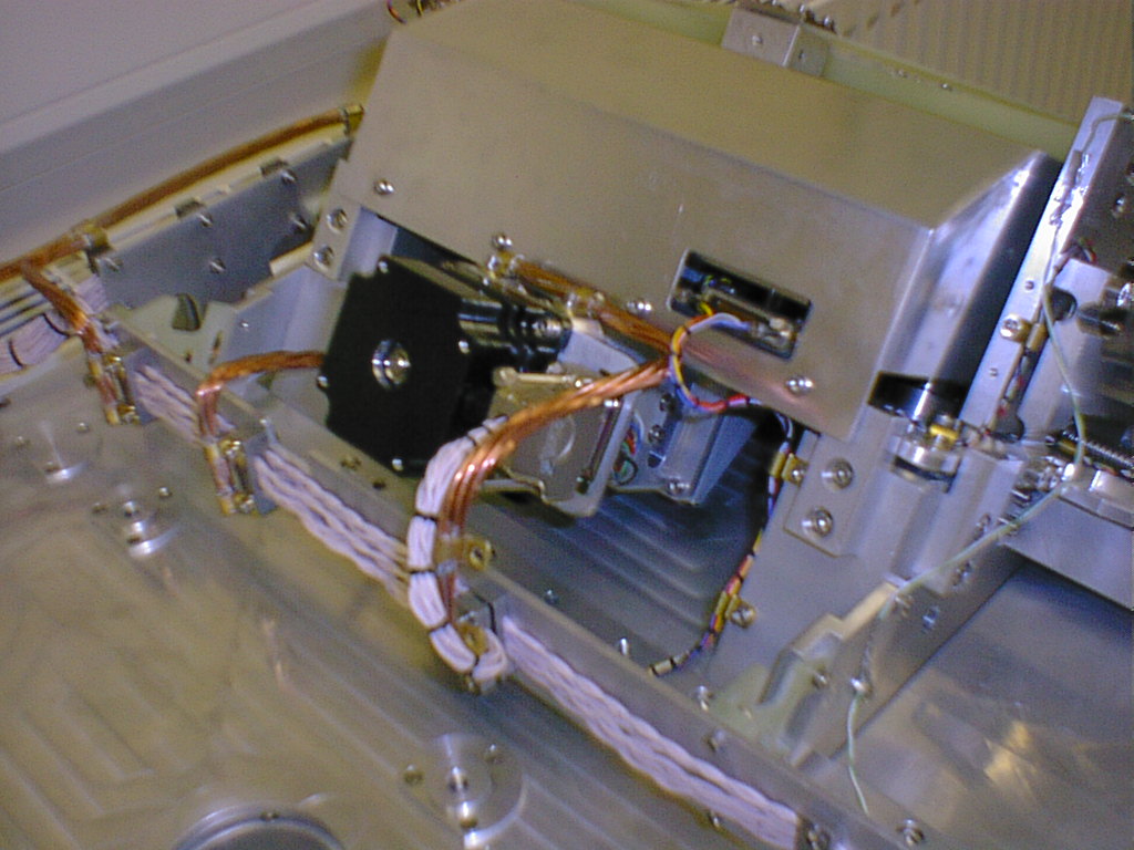
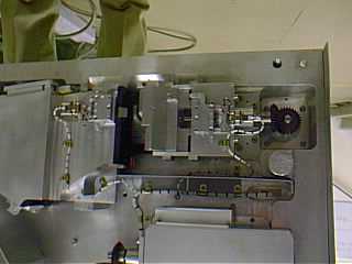
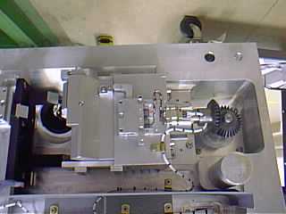
Both the motor assemblies have to be removed from the other side of the FOB, The inject motor assembly is located in a recess beneath the focus translation mechanisms and the extract motor protrudes from the FOB adjacent to the detector housing. To remove the motor assemblies first undo the M3 screws fixing the twisted copper braid thermal wicks and disconnect the stepper motor connectors then remove any aluminium tape and undo the four M4 socket head screws which secure the assemblies and baffle plates to the FOB.
|
|||
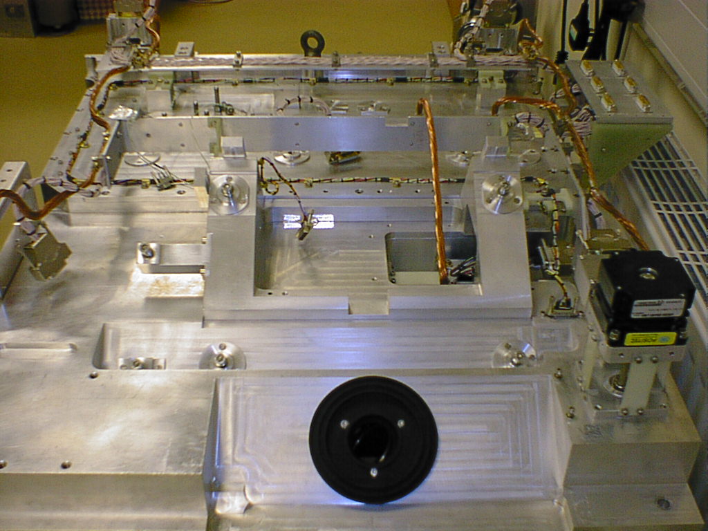
7 Removing cold pupil stop from the Front Optical Bench |
|||
|
7.1 Sit the front optical bench down on a flat level surface using the four support feet on the imager side of the front optical bench.
|
|||
|
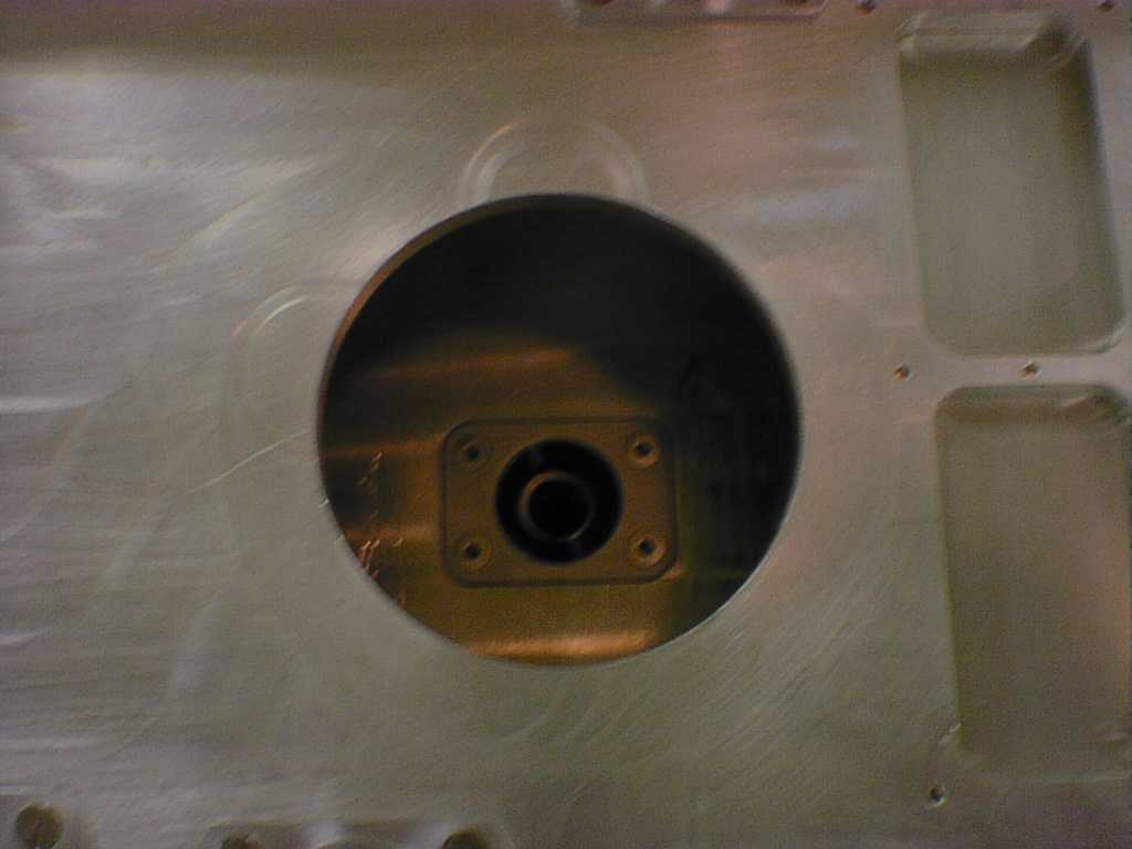
7.2 Ensure the imager inject mirror is in its spectroscopy position, manually retract the mirror by turning the motor coupling through the recess in the front optical bench if the mirror is observed to be in its imaging position. |
|||
|
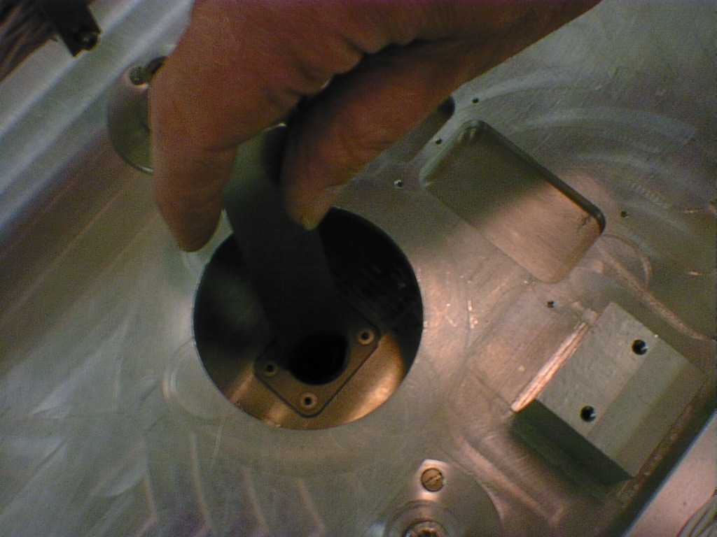
7.4 Remove the black clamp nut which is securingthe pupil stop in position through the access hole in the front optical bench using the tool supplied. Additional access through the filter drawer recess can be used. |
|||
|
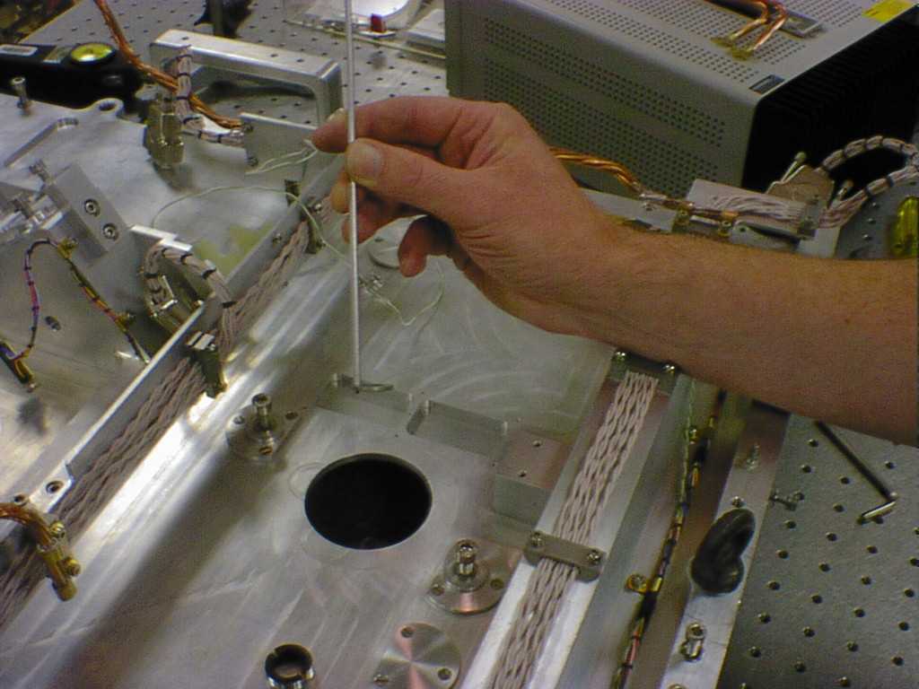
7.5 Remove the pupil stop through the access hole using the tool supplied, this is done by engaging the threaded end of the tool in one of the two tapped holes on the top of the pupil stop and withdrawing it from the recess carefully. The pupil stop has an orientation defining feature which is located in a slot in the pupil stop recess, this must be properly engaged when refitting the pupil stop. |
|||