| 3.2 Remove the window assembly,
inspect for water damage and store in a dry atmosphere.
|
|
|
|
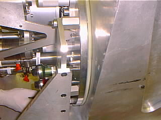
4.1 Rotate the cryostat until the interface
between the centre section and the front section is horizontal. Pull
out the two alignment dowels at the bottom corners which align
the front cover and hence calibration unit to the rest of
the cryostat.
|
|
4.2 Because access to bolts along the
side nearest the manipulator is restricted, these should be
removed first by rotating the cryostat such that the front
face is vertical.
|
|
4.3 Now rotate the cryostat until the
front face is horizontal. And attach the
four corner eye bolts and using two slings, one along each
side, attach to the overhead crane. Remove
the remaining bolts retaining the front cover.
|
|
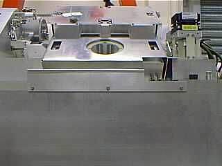
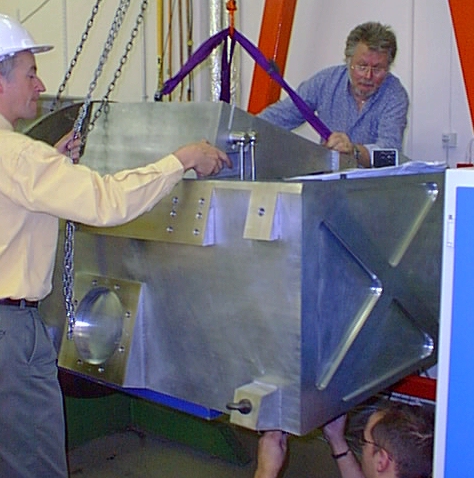
4.4 Lift off the front cover (mass
of front cover = 220kg) and lower it onto its flat storage
plate for later evacuation and storage. Note that the unused
set of fore-optics could be stored on the flat cover so you
may wish to leave the front section suspended until you have
removed them.
|
| Comments: | Done
by: | |
| Checked
by: | |
|
|
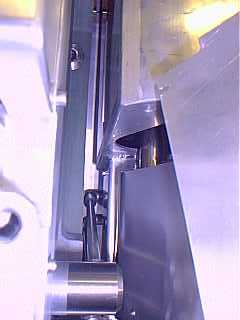
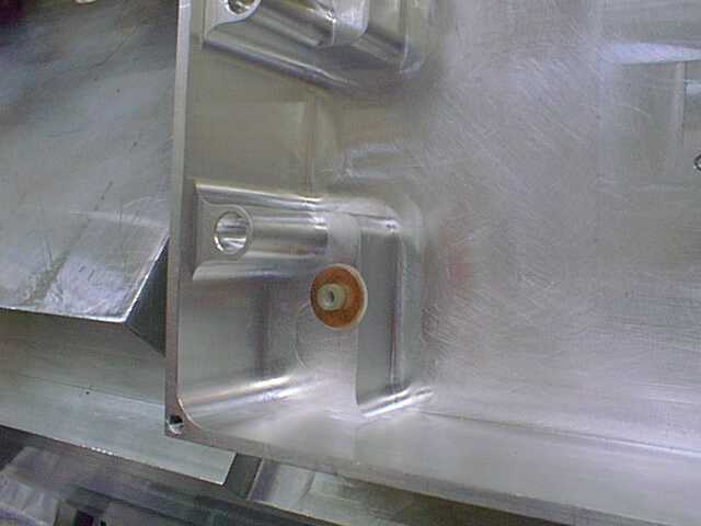
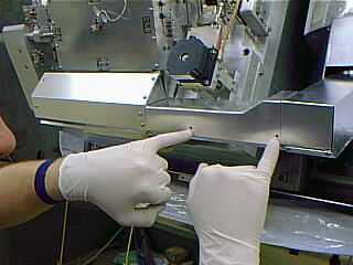
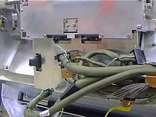
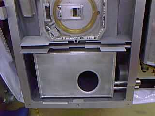
4.5 Check the front
section MLI blanket for damage, undo the tape and velcro pads
which secure it to the MLI on the centre section of the cold
optics, and remove for storage , ideally under vacuum.
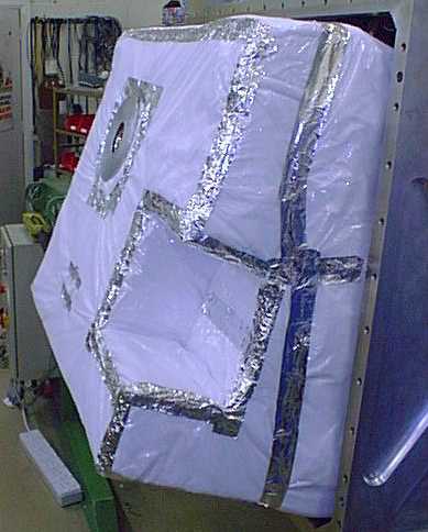
Figure 4.4 The front section multi-layer
insulation.
|
|
| Comments: | Done
by: | |
| Checked
by: | |
|
|
Radiation shield cover
4.6 Remove the sensor plate
hiding the Temperature sensor on the Front Radiation shield
and disconnect. The loose connector and lead can be taped
to the focus translation stage for safety. Replace
the plate on the front for safe keeping. With
the front face vertical, undo the sixteen screws on periphery
of shield, the three shorter screws at the copper thermal
wick and lastly the eight quick release catches to remove
the front section.
Store the screws and associated belleville washers in
the box provided, keeping the shorter wick screws separate.
Place the perspex cover over the UKIRT fore-optics by
reusing some of the screws holding on the front shiny plate.
|
|
| Comments: | Done
by: | |
| Checked
by: | |
|
 At
this point in the process it is recommended that all personnel
wear gloves to minimise dirt and contamination to the cryostat
innards. At
this point in the process it is recommended that all personnel
wear gloves to minimise dirt and contamination to the cryostat
innards. |
| DATE/TIME:
|
|
This procedure should only be undertaken by competent
personnel who have had previous instruction from a member
of the Michelle electronics team.
|
|
 It is not necessary to remove the whole of the 4K arm in order
to remove the array housing.
It is not necessary to remove the whole of the 4K arm in order
to remove the array housing.
|
|
First
check that the instrument is earthed through a low impedance
safety earth connection (see installing
the detector box and array)
|
|
|
| Connect an ESD lead from a conducting
mat to the copper block on the corner of the detector Box, ensure
that the detector box assembly is properly grounded through
the cryostat and that the person who will be removing the array
assembly is wearing a connected wrist strap, gloves and will
be standing on the mat |
|

|
|
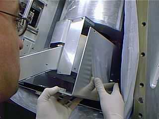
Remove the section of radiation shield in front of the
4K arm.
|
|
|
|
Undo the screws for the four clock and bias connectors,
there are two screws per connector, remember to slacken a
screw on either side of each connector alternately.
|
|
|
|
Remove the earth tags connected to the circular copper
cold block, disconnect the temperature sensor connector and
remove the right angle copper block which is attached to the
centre of the circular copper block at the end of a wick from
the 4K arm, replace the single M6 screw and invar bush in
the circular copper block for safe keeping.
|
 |
 |
|
|
|
Carefully move the cables, wires and wicks now hanging
from the end of the 4K arm to the side, remove the baffle
plate (three M3 socket screws) from along the gap between
the detector box radiation shield and the front optical bench
before undoing the eight M3 button head screws to remove the
main detector box radiation shield.
Do
not undo the four M3 socket cap screws.
|
|
|
|
Refit an ESD lead to the circular copper cold block.
|
|
|
|
To remove the detector box cover loosen all fourteen M3
slotted screws, Then remove the eight connector screws first,
followed by the six screws holding the cover to the detector
box, It will be necessary to temporarily disconnect the ESD
lead in order to remove this cover.
|
|
|
|
Fit shorting plugs to the four connector positions before
finally removing the ESD lead connection to the circular cold
block.
|
 |
 |
|
|
|
Undo the four M3 socket cap screws at the corners of the
inner gold array housing and carefully remove it from the
detector housing. Note the positions and arrangement of the
copper washers, G10 spacers and mylar insulators these should
be replaced in the detector housing along with the screws
for safe keeping.
|
 |
|
Cover over the square hole into the array housing and
transfer it to an ESD dissipative bag then store it away safely,
preferably in a clean room environment or if one is not available
then in a protected dry atmosphere.
|
|
| Comments: | Done
by: | |
| Checked
by: | |
|
|
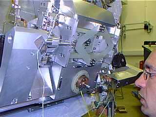
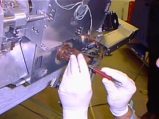
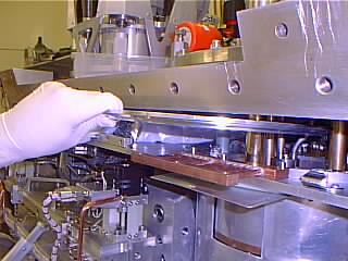
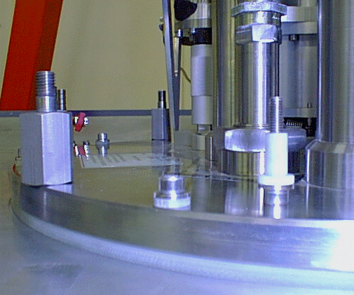
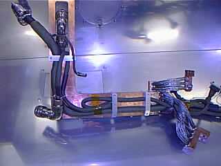
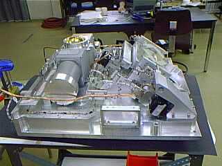
5.3 Disconnect the array cables
at the four connectors (2 jackscrews each) at the back of
the detector box, the connector to the array temperature sensor
and heater and the small black connector to the DT470 temperature
sensor.
Immediately attach four 1 million Ohm grounding paths, running
from the detector focus and translation mechanism to locations
as listed below, and as shown in Figure 5.3.
-
To the top of the Joule-Thomson cooler,
which should in turn be connected to the telescope ground.
-
To a conducting mat placed on which the
person installing the detector box should stand.
-
To a wrist strap on the installer.
-
To the grounding stud on the gold detector
box or (as shown in the Figure) to the base of the detector
cold finger.
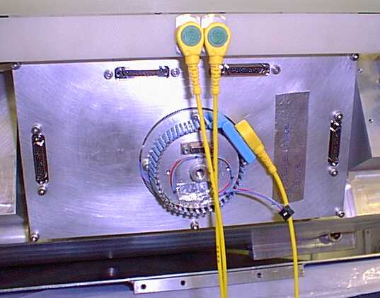
Figure 5.3 Grounding the detector
box when the detector cables are not connected. (Cooling
arm has been removed).
|
| Comments: | Done
by: | |
| Checked
by: | |
|
|
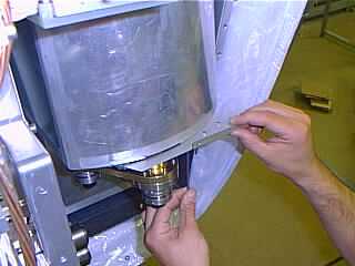
5.4 Unscrew the single bolt with its
Invar washer which holds the copper block to the back surface
of the array, and remove the 25K shield by undoing its 3 screws.
|
| Comments: | Done
by: | |
| Checked
by: | |
|
|
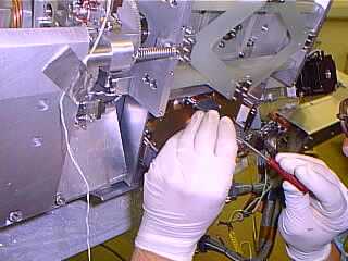
5.5 Undo the screws which hold the array
connectors to the inside of the array housing cover, and then
remove the array housing cover by undoing its 6 screws. (see
Figure 5.3).
|
|
| Comments: | Done
by: | |
| Checked
by: | |
|
|
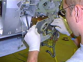
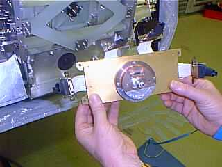
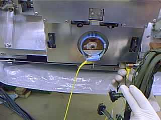
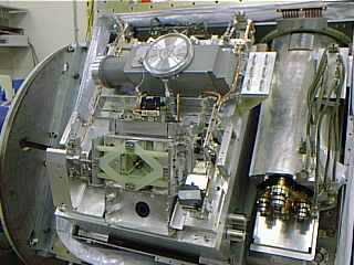
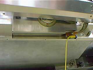
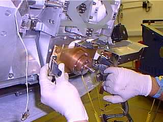
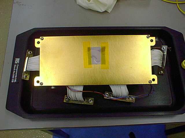
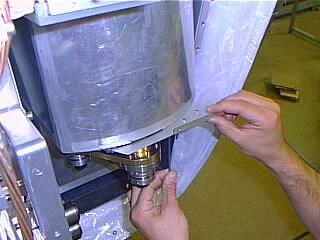
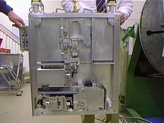
5.6 Remove the gold detector box by undoing
its four screws and their insulating washers, and transfer
it to a grounded antistatic tray or bag for immediate transfer
to a clean and electrically safe area. The
aperture in the gold box over the array should be covered.
Figure 5.6 The gold detector box
ready for removal and storage (should be grounded!).
|
| Comments: | Done
by: | |
| Checked
by: | |
|
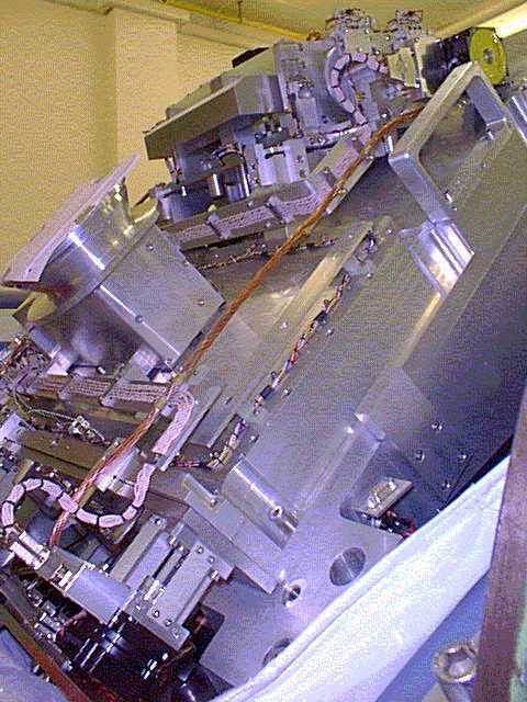
6 Removing the 4K arm
(30 minutes)
|
|
|
|
This
Procedure should only be undertaken by competent personnel
who have had previous instruction from a member of the Michelle
electronics team.
|
|
First
check that the instrument is earthed through a low impedance
safety earth connection (See
installing the detector box and array)
|
|
|
|
Connect an ESD lead from a conducting mat to the copper
block on the corner of the detector box. Ensure that the detector
box assembly is properly grounded through the cryostat and
that the person who will be removing the 4K arm is wearing
a connected wrist strap, gloves and will be standing on the
mat.
|
 |
 |
 |
|
Undo the button head screws from end section of radiation
shield and remove both components, replace the screws in copper
arm and secure the two pieces of radiation shield together
for safe keeping.
|
|
|
|
Remove the front and side sections of the box surrounding
the gold 4K plate at bottom of JT radiation shield by undoing
the socket head screws from along the bottom and back edges.
|
|
|
|
Remove last three pieces of the radiation shield around
the copper arm and the curved pieces from around the gold
4K plate. Note
that one of these pieces is fixed by acorn nuts to studs on
the plate and the other is only guided by screws at the rear
left between the JT radiation shield and the main optical
bench.
|
 |
|
All the pieces of the 4K arm radiation shield should now
have been removed, the curved shaped bracket attached to the
bottom of the JT radiation shield need only be removed if
you intend removing the JT system from the
cryostat.
|
 |
|
Undo the screws and disconnect the four clock and bias
connectors, there are two screws per connector, remember to
slacken a screw on either side of each connector alternately.
|
|
|
| Remove the earth tags
connected to the circular copper cold block, disconnect the
temperature sensor connector and remove the right angle copper
block which is attached to the centre of the circular copper
block at the end of the wick from the 4K arm, replace the single
M6 screw and the Invar bush in the circular copper block for
safe keeping. |
 |
| Carefully remove the
cable, wired and wick now hanging from the end of the 4K arm
to one side in order to fit shorting plugs to the four connector
positions. |
|
|
Attach another ESD
lead to the circular copper cold block, so that the ESD lead
to the copper block on the corner of the detector box can safely
be removed, This then allows you to undo the two M5 socket head
screws with Invar spacers and remove the copper block which
joins the 4K arm to the detector box by a wick.
Remember
to replace the screws and spacers in the detector box for safe
keeping. |
|
|
| Slacken the three
jam nuts then carefully disconnect the right-angled connectors
from the bottom of the JT system wiring tubes. Also disconnect
the 15 way D type connector which is located on the gold 4K
plate. |
|
|
| Support the weight
of the arm and undo the seven M6 screws with Invar spacers which
are securing it to the angled face on the bottom of the 4K plate. Then
carefully remove the arm. REMEMBER to replace the
screws and spacers. |
 |
| Clean off any cryogenic
conducting grease from the arm and angled face of the 4K plate,
before storing the arm somewhere safe. |
| Comments: | Done
by: | |
| Checked
by: | |
|
|
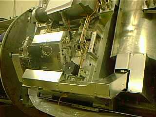
6. Remove the front and right
hand side covers (Al sheet) from the J-T cooler. (Note that
one of the covers is only guided by the screws at the rear
left - IRB). Then remove all shields from the copper arm.
|
| Comments: | Done
by: | |
| Checked
by: | |
|
| 6.
Remove the 7 fixing screws holding the arm to the base of the
J-T cooler. They all have Invar washers and there is an Indium
sheet sandwiched between the arm and the cooler. |
| Comments: | Done
by: | |
| Checked
by: | |
|
| DATE/TIME: |
|
First
Ensure that the 4K arm and its radiation
shield have been removed.
|
|
|
|
Remove the curved shape bracket from the bottom of the
JT radiation shield.
|
|
|
| Undo 8 M4 screws from slit ring
inside the cryostat at the cold head end of JT system. Access
for the rear two screws can be obtained by retracting the top
connector panel at the services are adjacent to the grating
drum cover. |
|
|
|
Remove the two halves of split ring and the 0-ring through
front of cryostat.
|
|
|
|
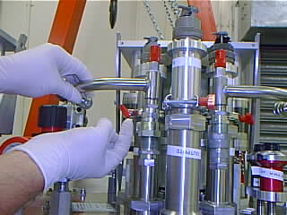
Ensure that any pressure is released from the JT system
then remove the Helium pressure relief bends and fit
protection caps.
|
|
|
|
Rotate cryostat until JT system is horizontal.
|
|
|
|
Position the JT handling frame on the lifting trolley
then line up the frame with the six hexagonal stand offs on
the JT plate then secure in place using nuts.
|
|
|
|
|
Undo the nine M5 screws with Invar spacers, G10 washers
and G10 bushes from cryostat plate fitting the alignment pins
provided sequentially as the screws are removed.
|
|
|
| Slowly withdraw the JT system
from the cryostat using both the frame and trolley, slightly
raise or lower the trolley if required and guide from beneath. |
|
|
|
Once JT system has been retracted, slide
the frame back on the trolley and secure with clamps.
|
| Comments: | Done
by: | |
| Checked
by: | |
|
| DATE/TIME: |
| If desired, confirm
the operation of the Front End mechanism before disassembly. |
|
|
|
|
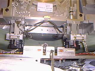
| 8.1 Remove
all six stepper motor cables (check first that the control racks
are depowered) and the one status cable at the the interface
to the radiation shield. Also remove the long panel
covering the JT side of the joint between the FOB and the MOB |
| Comments: | Done
by: | |
| Checked
by: | |
|
|
|
| 8.2 Disconnect
the twisted copper strands at the filter wheel motors. |
| Comments: | Done
by: | |
| Checked
by: | |
|
|
|
| 8.3 Rotate
the instrument until the interface between the front optical
bench and the main optical bench is 5 degrees past vertical
with Array end sticking out most. |
| Comments: | Done
by: | |
| Checked
by: | |
|
|
|
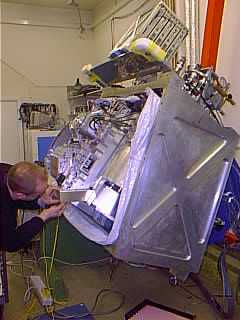
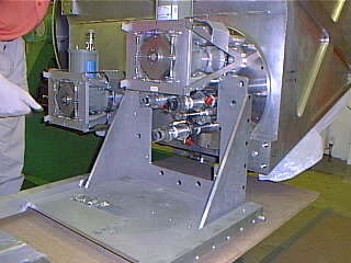
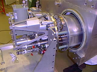
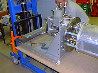
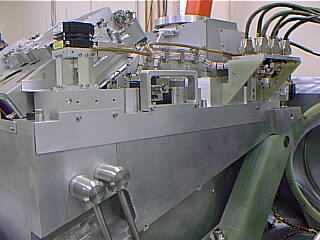
| 8.4 Attach
an eyebolt and shackle to the upper-centre of the front optical
bench and support the bench on a single hook using the overhead
crane (~50kg). |
| Comments: | Done
by: | |
| Checked
by: | |
|
|
|
|
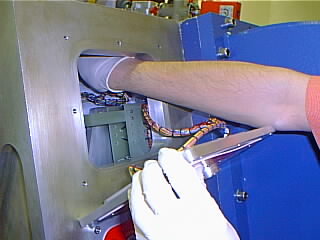
| 8.5 Undo
the six M8 bolts, with the invar washers, three down each side
of the FOB that attach it to the MOB and swing it clear using
the two handles, and the trolley facility on the crane. Replace
the bolts and washers in the MOB for safe keeping. Lower
the FOB gently to lie horizontally on a storage table by lifting
the array end whilst the rear end is lowered. This needs one
person per handle. The FOB has four feet to stand
on.
Figure 8. Removing the Front Optical
Bench.
|
|
| Comments: | Done
by: | |
| Checked
by: | |
|
|
|
|
8.6 Cover the exposed field rotator optics
and the opening to the spectrometer camera with the perspex
covers provided. (Spectrometer cover needs to be
taped in place.)
|
|
| Comments: | Done
by: | |
| Checked
by: | |
|
| Service operations
and removing modules from the front optical bench are described
in Front Optical Bench. |
| DATE/TIME: |
|
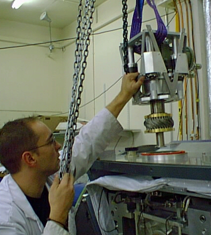
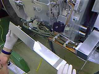
11.1 Position the cryostat with the grating
drum at the top and the interface between the grating and
the centre section horizontal. Remove the bolts connecting
the grating drum vacuum cover to the centre section.
Note
that as with the front cover, the screws nearest the manipulator
may need to be removed first with the interface surface vertical
to ease access.
Install eyebolts in the grating drum cover, lift it off
(mass = 100kg), and lower it onto a table. (see Figure 11.1).
Figure 11.1 Removing the grating
drum vacuum cover
|
| Comments: | Done
by: | |
| Checked
by: | |
|
| 11.2 Inspect grating
multi-layer insulation (MLI) blanket for damage and remove for
possible storage under vacuum. (Retained by velcro
pads.) |
| Comments: | Done
by: | |
| Checked
by: | |
|
| 11.3 Undo bolts
connecting grating radiation shield to centre section radiation
shield and remove radiation shield. Store the
screws and belleville washer pairs in the box provided. |
| Comments: | Done
by: | |
| Checked
by: | |
|
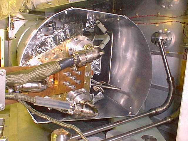
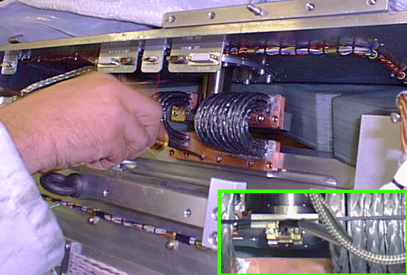
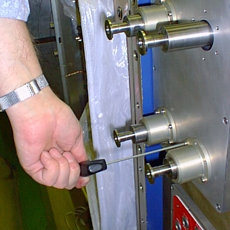
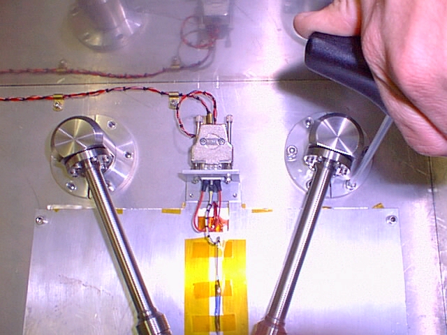
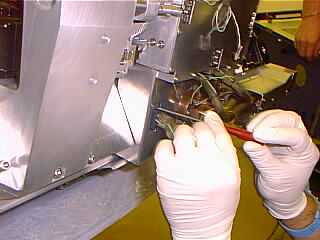
11.4 Unplug the
two motor cables, one status cable and two thermal wicks (shown
in Figure x) from the motor side of the grating drum. All cables
are green shrouded.
- Ensure
all motor drive cards have been depowered before disconnecting
motor cables.
-
Leave the wavelength drive motor wick attached at the motor
end to help in drum installation.
-
The wick attached to the motor which rotates the drum is
tricky to access
(see Figure 11.4).
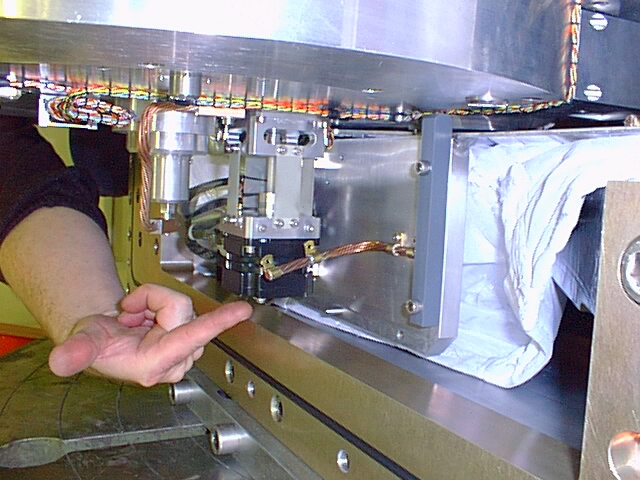
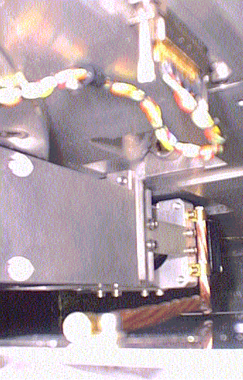
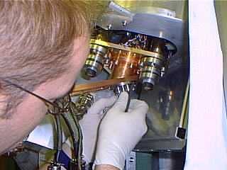
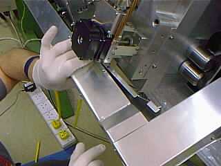
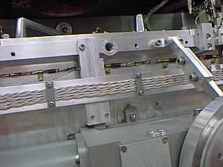
Figure 11.4 The thermal wicks on
the grating drive motors. The hand is pointing to the wavelength
drive wick at the left (note the grey snubber bar on the radiation
shield). The right hand picture shows the difficult to access
grating exchange motor wick.
|
| Comments: | Done
by: | |
| Checked
by: | |
|
|
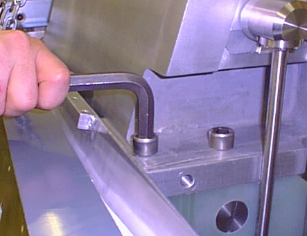
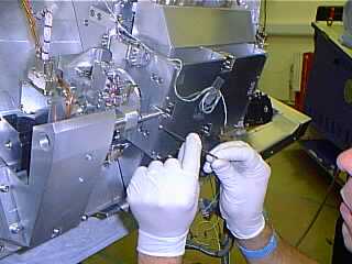
11.5 Fit five grey coloured bar shaped
snubbers to the centre section radiation shield using the
radiation shield screws to finger tightness. (they act as
guides when withdrawing the drum). Each snubber is numbered
as is its location on the radiation shield.
|
| Comments: | Done
by: | |
| Checked
by: | |
|
|
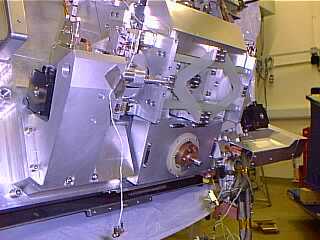
11.6 Fit two lifting shackles
(the third is not required) to the drum on the side nearest
to the motors, undo the four captive bolts holding it to the
centre section using the special tools provided (two Allen
key ended bars 57cm and 67cm long) and lift it out of the
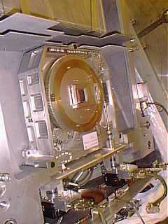
centre section as shown in Figure 10.6 (drum mass 135 kg).
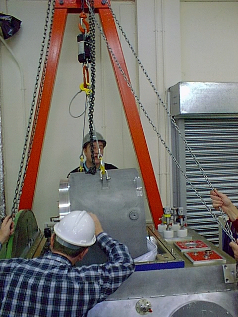
Figure 11.6 Removing the grating
drum.
|
| Comments: | Done
by: | |
| Checked
by: | |
|
|
11.7 As soon as the drum
is raised far enough mount the protective perspex cover over
the open face of the centre section to protect the spectrometer
collimator and camera optics. Four short
screws are needed.
|
| Comments: | Done
by: | |
| Checked
by: | |
|
|
11.8 Unplug and remove the
three grating exchange motor drive and datum sensor cables
from the centre section.
|
|
| Comments: | Done
by: | |
| Checked
by: | |
|