| DATE/TIME: |
| 4.1 Turn the vacuum
vessel until the interface with the front optical bench is horizontal
and at the top. Lower the main optical bench whilst guiding
the nitrogen fill pipes through the holes in the vacuum vessel
until it is a few inches above the truss feet.
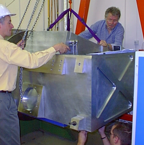
Figure 4.1 Lowering
the main optical bench into the vacuum vessel, with the fill
tubes being guided through the radiation shield.
|
| Comments: | Done
by: | |
| Checked
by: | |
|
|
4.2 Fit the collet clamps to the
nitrogen fill tubes and push them into the holes in the radiation
shield.
|
|
| Comments: | Done
by: | |
| Checked
by: | |
|
| 4.3 Lower the main optical
bench the final inches onto the truss feet and tighten the eight
M16 x 70mm bolts to 140Nm.
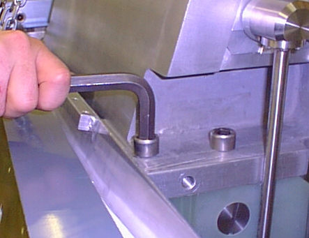
Figure 4.3 Tightening the bolts
holding the MOB onto the truss.
|
| Comments: | Done
by: | |
| Checked
by: | |
|
| 4.4 Tighten the
six bolts holding the collet clamp pairs on each of the two
nitrogen fill tubes onto the radiation shield. |
|
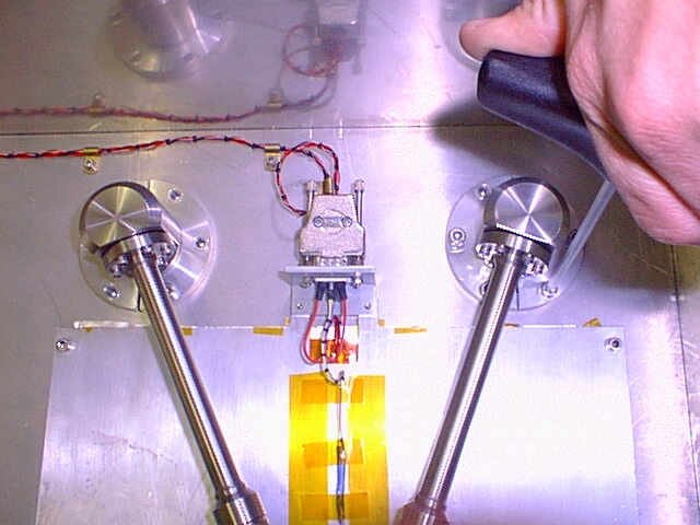
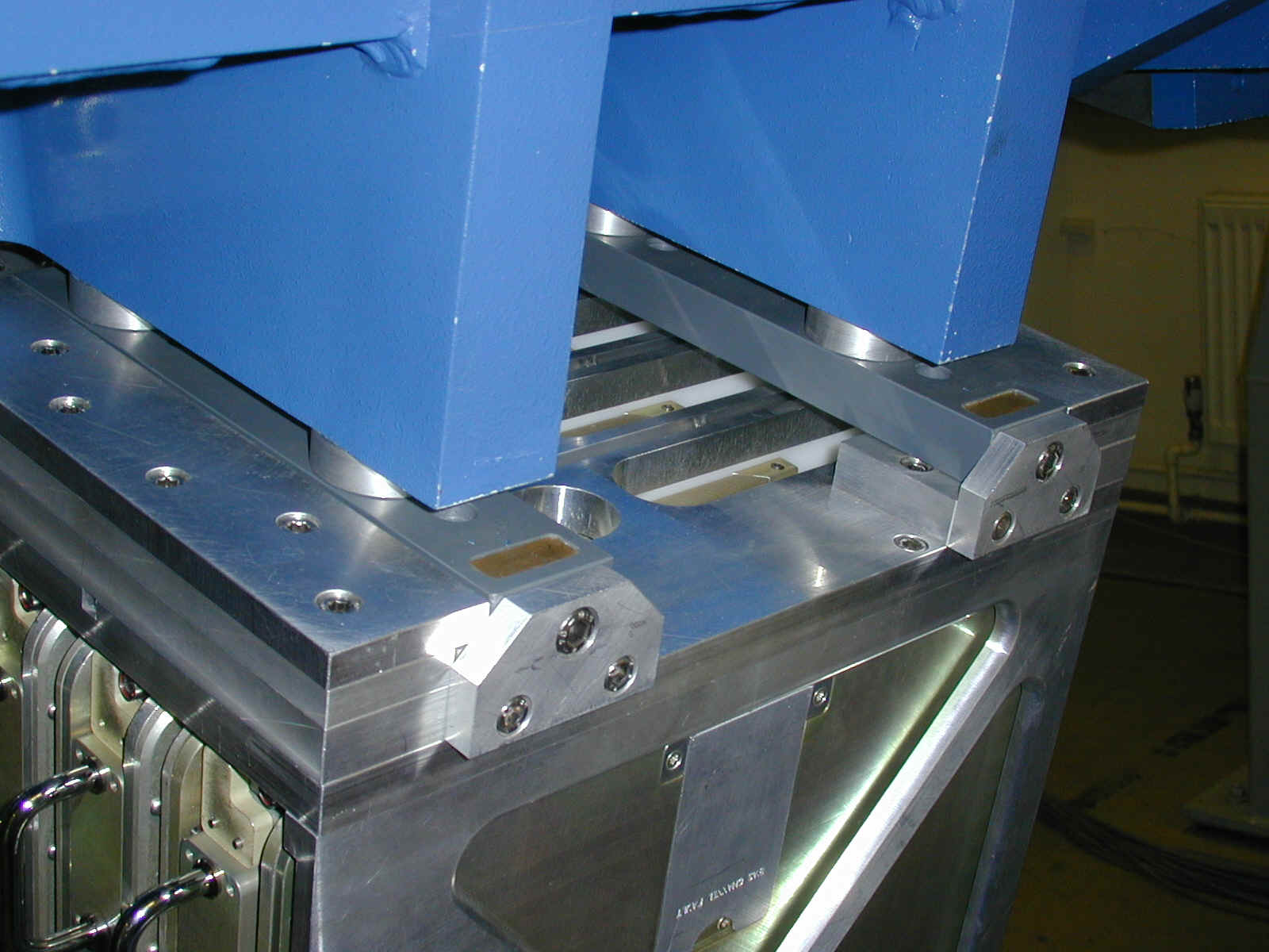
Figure 4.4 Bolting down the collet
clamps from the MOB nitrogen fill tubes. Note that the Radiation
Shield Heater panel shown here now has clamping bars across
the backing plate.
|
| Comments: | Done
by: | |
| Checked
by: | |
|
| 4.5 Install the vacuum fittings
and the supporting collars for the MOB nitrogen fill tubes where
they enter the vacuum vessel. Finally add the white plastic
protection sleeves.
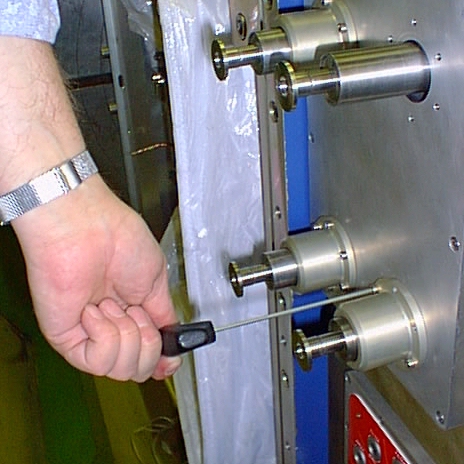
Figure 4.5 Installing
the support collars on the nitrogen fill tubes.
|
| Comments: | Done
by: | |
| Checked
by: | |
|
| DATE/TIME: |
| 5.1 Lower the cooler into
the vacuum vessel (Figure a) and tighten the six mounting bolts
(Figure b).
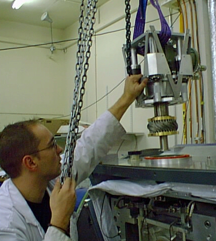
Figure 5.1a. Lowering the CTI1020
cold head in the vacuum vessel. (Note that the copper wick
assembly has now been replaced by a solid copper sleeve)
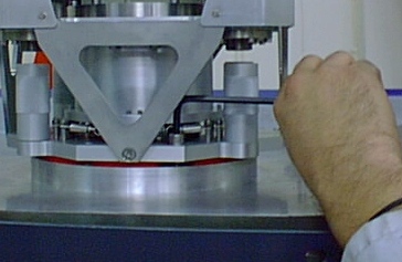
Figure 5.1b. Bolting the CTI1020
cold head onto the vacuum vessel.
|
| Comments: | Done
by: | |
| Checked
by: | |
|
|
5.2 Tighten the eight screws which
mount the the copper collar on the radiation shield to the
copper sleeve attached to the 1st stage of the coldhead. These
should be torqued to M6 setting.
(NEW PHOTO REQD)
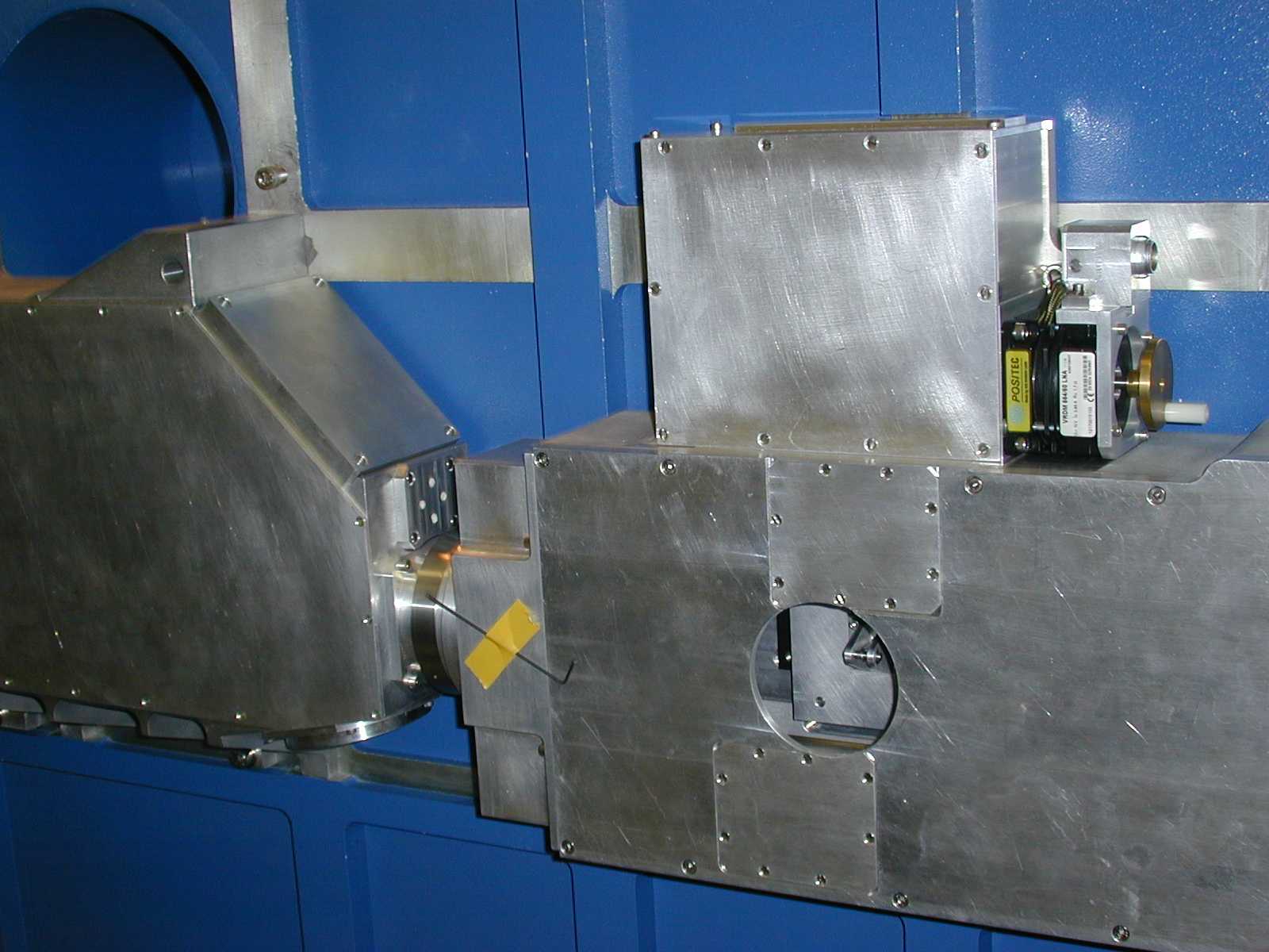
Figure 5.2. The second stage
adapter plate can be seen at the end of the 2nd stage column,
protruding through the radiation shield. The wicking bundles
go from the adapter plate to the copper block which is bolted
to the main optical bench at the bottom of the picture. The
circular collar at the top clamps the radiation shield onto
the sleeve from the first stage. The first and second stage
temperature sensors are shown.
|
| Comments: | Done
by: | |
| Checked
by: | |
|
| Fit the superinsulation collar around the
copper sleeve from the first stage of the coldhead and secure
with lacing tape. |
|
5.3 Install the Radiation Shield
temperature sensor on the copper plate behind the field rotator
motor and attach connector. (This may have not
been removed as now clear of area.)
|
| Comments: | Done
by: | |
| Checked
by: | |
|
|
5.4 Tighten the six 6-32UNC screws
and their invar spacers which hold the 2nd stage adapter plate
onto the end of the 2nd stage pillar (to required torque setting).
This is an awkward operation requiring a short Allen key.
|
| Comments: | Done
by: | |
| Checked
by: | |
|
|
5.5 Install the temperature sensor
on the second stage adapter plate and attach connector.
|
| Comments: | Done
by: | |
| Checked
by: | |
|
|
5.6 Install the 2nd stage wicking
between the adapter plate and the main optical bench (see
Figure 7). The screws are M5 with a torque setting of ...
|
| Comments: | Done
by: | |
| Checked
by: | |
|
| DATE/TIME: |
| 6.1 Rotate the cryostat
to a position where the Joule-Thomson can be wheeled into place
horizontally on its trolley. If fitted, remove the blanking
plates in the centre section of the vacuum vessel and radiation
shield, and carefully guide the J-T cooler into the cryostat.
Figure 6.1.
Installing the Joule-Thomson cooler in the centre
section of the vacuum vessel. Note that it now comes fitted
with it's own Radiation Shield which will obscure the inner
pipework. This operation will be done in Hawaii using the
Handling Trolley.
|
| Comments: | Done
by: | |
| Checked
by: | |
|
| 6..2 Install the electrically
insulating washers and inserts and then tighten the bolts connecting
the cooler to the vacuum vessel.
Figure 6..2.
The electrically insulating inserts which screw the Joule-Thomson
cooler into the centre section of the vacuum vessel.
|
| Comments: | Done
by: | |
| Checked
by: | |
|
| 6.3 Fit the o-ring around
the interface at the radiation shield and secure in place with
the split ring. Access to the rear section requies
removing the connector plate as shown.
Figure 6.3 The interface between
the J-T cooler first stage and the radiation shield. The green
circle marks the position of the electrically insulating moat.
(NEW PHOTO req'd) Check that the J-T cooler is
electrically isolated from the cryostat. Fit the
small flat shield to the end of the J-T radiation shield.
|
| Comments: | Done
by: | |
| Checked
by: | |
|
7 Installing the Slit
wheel/Field Rotator Assembly (20 mins)
|
| Orientate the cryostat to have the coldheads
on the underside per figure. Remove the perspex cover
covering the Collimator entrance, these screws hold in the slit/FRot
assembly. You may need to loosen the screws retaining
the transverse light baffles in the Main Optical Bench are loose. Make
sure the status cables for both Field Rotator and in particular
the Slit Wheel are attached to the assembly. Check
also that light path through array is clear. |
| Comments: | Done
by: | |
| Checked
by: | |
|
| Fit the Assembly into the Main Optical Bench
making sure it is pushed snugly into it's "corner"
before fitting and securing the three retaining bolts. Note
that the proximity of the light baffling at the assembly's motor
plate can lead to an improper location. Take
care to avoid damaging cabling on the radiation shield. |
| Comments: | Done
by: | |
| Checked
by: | |
|
| If necessary tighten the screws securing the
transverse light baffles between the Slit/Field Rotator assembly
and the Nitrogen tank. Fit the thermal wicks to each motor,
connect the two motor cables at both ends and terminate the
status cables at the Radiation Shield end. |
|
| Comments: | Done
by: | |
| Checked
by: | |
Fit tape along gaps at the rearmost of the motor plate
as this is a known light leak area.
|
| DATE/TIME: |
| 8.1 The filter wheels
are light enough to be lowered into the slot in the FOB by hand
as shown below. The FOB is supported as described in Section
8.2. The two motor cables, a status cable and the temperature
sensor on one Filter wheel should then be reconnected.
Figure 8.1 Lowering
the filter wheel assembly into the front optical bench. (Alignment
features highlighted)
|
| Comments: | Done
by: | |
| Checked
by: | |
|
| 8.2 Remove the perspex
covers over the field rotator optics and the opening to the
spectrometer camera through the Nitrogen can. |
| Comments: | Done
by: | |
| Checked
by: | |
|
| 8.3 Referring to Figure
12, rotate the instrument such that the mating face of
the MOB is parallel to the FOB as it hangs on the single support.
Using the trolley facility on the hoist move the FOB into engagement
with the MOB - the FOB feet help with the alignment but manual
guidance is also required. Attach the FOB to the MOB by partially
tightening the six bolts, three per side.
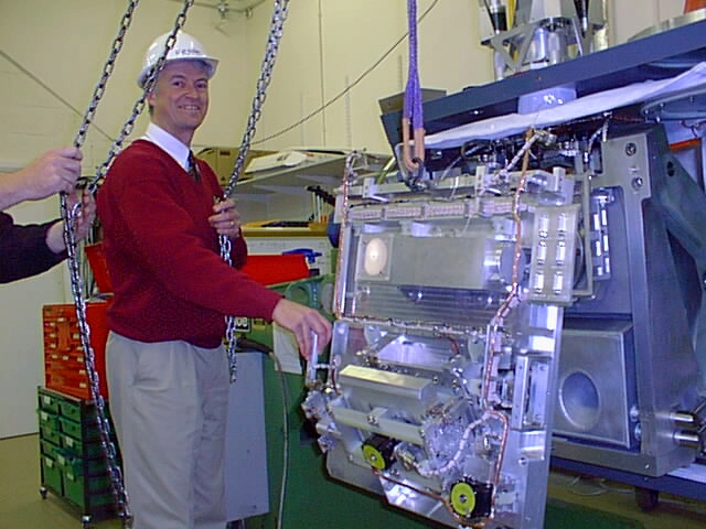
Figure 8.3. Mounting the Front Optical Bench onto
the Main Optical Bench.
|
| Comments: | Done
by: | |
| Checked
by: | |
|
| 8.4 Rotate the instrument
to an orientation where the weight of the FOB helps pushes it
into the corner defined by the three reference pads shown in
Figure 13. The six bolts(with Invar washers) will need to be
loosened first for positioning before being tightened (M8,
36.2Nm).
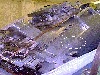
Figure 8.4. Aligning the FOB to the MOB. The three
reference pads are circled in green in the lower picture;
the filter wheel assembly and fore-optics are not shown for
clarity.
|
| Comments: | Done
by: | |
| Checked
by: | |
|
| 8.5 Connect the motor
thermal wicks at the filter wheel motors. Replace the long side
panel covering the joint between FOB and MOB. This
should then be taped up. |
| Comments: | Done
by: | |
| Checked
by: | |
|
| 8.6 Connect all six
stepper motor cables (making sure the control racks are depowered)
and one datum status cable that interface the FOB to the cabling
on the centre section of the radiation shield. |
| Comments: | Done
by: | |
| Checked
by: | |
|
|
|
|
10. Installing the Detector
Box and array
|
| DATE/TIME: |
|
 The detector in its gold coloured box should normally be mounted
as late as possible in the assembly procedure to avoid damage.
It should be stored in a protected, dry atmosphere and carried
in a container that keeps it electrically contacted to ground
through an approximately 1 million Ohm resistance (to prevent
fast changes in potential difference and hence high instantaneous
current flow).
The detector in its gold coloured box should normally be mounted
as late as possible in the assembly procedure to avoid damage.
It should be stored in a protected, dry atmosphere and carried
in a container that keeps it electrically contacted to ground
through an approximately 1 million Ohm resistance (to prevent
fast changes in potential difference and hence high instantaneous
current flow).
|
10.1 Start
off by installing four 1 million Ohm grounding paths running
from the detector focus and translation mechanism to locations
as listed below, and as shown in Figure 10.1.
- To the top of the Joule-Thomson cooler, which should
in turn be connected to the telescope ground.
- To a conducting mat placed on which the person installing
the detector box should stand.
- To a wrist strap on the installer.
- To the grounding stud on the gold detector box.
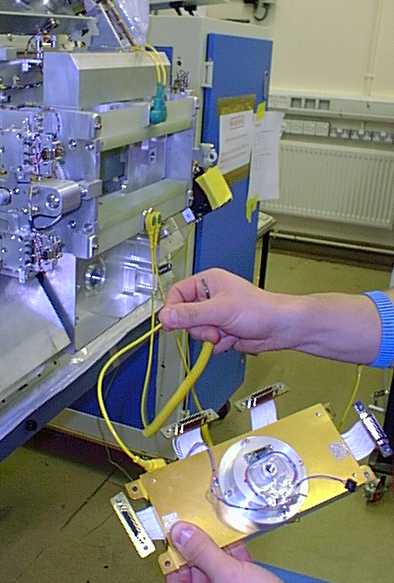
Figure 10.1. The detector box
and translation mechanism grounding scheme for electrically
safe installation.
|
| Comments: | Done
by: | |
| Checked
by: | |
|
| 10.2 Mount
the detector box into the translation mechanism using the four
screws, ensuring that the two are electrically isolated from
each other using the G10 tube inserts, and drawing film under
the copper washers (as shown in Figure 10.2).
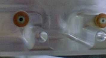
Figure 10.2. Detail of the mounting
screw arrangement for the detector box.
|
| Comments: | Done
by: | |
| Checked
by: | |
|
| 10.3 Use
a voltmeter to check that the detector box is isolated from
the optics. |
| Comments: | Done
by: | |
| Checked
by: | |
|
| 10.4 Attach
the cover to the detector box, feeding through and screwing
down the four D-type connectors. |
| Comments: | Done
by: | |
| Checked
by: | |
|
| 10.5 Connect
the detector cables without delay. If this is not possible,
ensure that the detector box's voltage cannot float, for example
using the scheme shown in Figure 10.5.
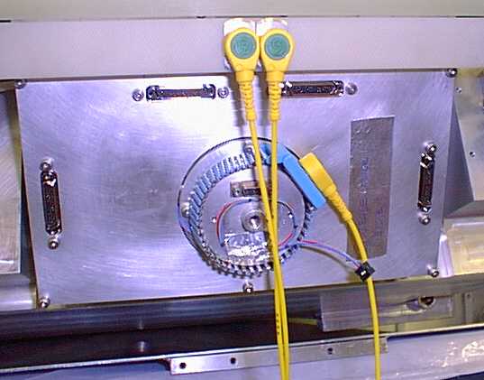
Figure 10.5. Grounding the detector
box when the detector cables are not connected.
|
| Comments: | Done
by: | |
| Checked
by: | |
|
| 10.6 Install
the silver foil covered radiation shield over the detector housing
as shown in Figure 10.6.
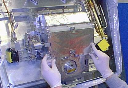
Figure 10.6. Installing the Detector
Box's 25K Radiation Shield
|
| Comments: | Done
by: | |
| Checked
by: | |
|
| 10.7 Securely
bolt the copper arm shown in Figure 18 onto the '4K' stage of
the Joule-Thomson cooler. Attach the two sets of copper wicks
leading from it, one to the detector cold finger assembly and
the other to the detector box.
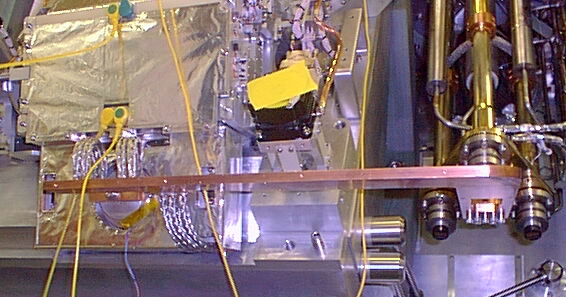
Figure 10.7. The copper arm from
the J-T Cooler to the detector box.
|
| Comments: | Done
by: | |
| Checked
by: | |
|
| 10.8 Connect
the cable assembly, running along the copper arm from the J-T
stage to the detector box, as shown in Figure 10.8.
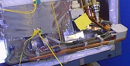
Figure 10.8. The detector cable
assembly mounted on the copper cooling arm.
|
| Comments: | Done
by: | |
| Checked
by: | |
|
| 10.9 Next, build
up the 4K radiation shielding around the 4K stage of the J-T
cooler and the copper arm (Figures a and b). Note that this
must not come in thermal contact with any elements which are
being cooled to 25K.
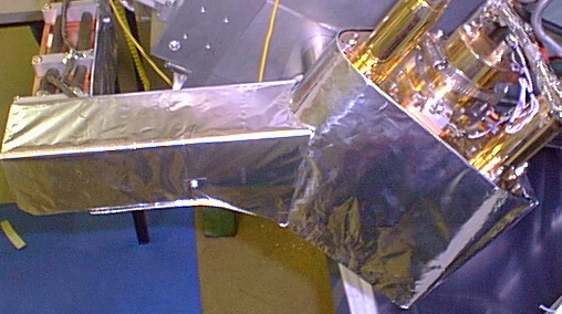
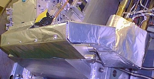
Figure 10.9a and 10.9b. The double
layer aluminium 4K radiation shield foil radiation.
|
| Comments: | Done
by: | |
| Checked
by: | |
|
| 10.10 The final
appearance of the detector box and J-T cooler is shown in Figure
10.10.
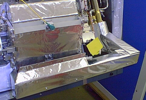
Figure 10.10. The assembled detector
box, with the 4K cooling circuit installed.
|
| Comments: | Done
by: | |
| Checked
by: | |
|
| DATE/TIME: |
| 11.1 Before
closing the cryostat front end the system should be connected
to the Cryostat Control system to confirm the performance of
the various Front end mechanisms. A further check is required
to confirm that the Temperature sensors are connected. (A complete
status switch check can be performed using the Status cable
break-out box if desired). |
11.2 Mechanism Check
Using CCS dm screens do a force datum on the mechanisms
in turn. One person should observe the mechanism
itseld for motion, noise etc., whilst the other should observe
the dm screen for datum switch operations etc.
Before driving the motors remove all perspex films
used to cover the motor shafts.
|
Mechanism
|
Test 1
|
Test 2
|
Test 3
|
Test 4
|
| Slit Wheel |
|
|
|
|
| Field Rotator |
|
|
|
|
| Filter Wheel A |
|
|
|
|
| Filter Wheel B |
|
|
|
|
| Imager Inject |
|
|
|
|
| Imager Extract |
|
|
|
|
| Focus Drive |
|
|
|
|
| Translation Drive |
|
|
|
|
| Comments: | Done
by: | |
| Checked
by: | |
|
11.3 Temperature Sensor Check
Indicate temperature reading either directly from scanners
or from CCS
|
Temperature Monitor A
|
Temp (K)
|
Temperature Monitor B
|
Temp (K)
|
| 1 Rad Shield Nitrogen Can |
|
1 JT Stage 1 |
|
| 2 GM Stage 1 |
|
2 JT Stage 2 |
|
| 3 Rad Shield Grating Cover |
|
3 JT Stage 3 |
|
| 4 GM Stage 2 |
|
Unused |
|
| 5 Rad Shield Front |
|
Unused |
|
| 6 Grating Assembly |
|
6 Filter Wheel Motor |
|
| 7 Slit/Field Rotator housing |
|
Unused |
|
| 8 Imager Stop |
|
Unused |
|
Lakeshore 330
|
Temp (K)
|
| A Array cold block |
|
| B Array substrate |
|
| Comments: | Done
by: | |
| Checked
by: | |
|
| 11.4
Remove all protective covers and shields from the optical
path and then mount the front section of the radiation shield,
securing the quick-release latches. Now fit and tighten the
16 screws (with belleville washers) to a torque of
4 Nm, followed by the four screws which secure the copper
wick from the central radiation shield (also 4NM torque). |
| Comments: | Done
by: | |
| Checked
by: | |
|
| 11.5
Attach the temperature sensor to the front radiation shield,
accessible through the hole in the Shield and close off the
hole. |
| Comments: | Done
by: | |
| Checked
by: | |
|
| 11.6 Install
the front section's MLI blanket.. Check for electrical short
circuits between the Joule-Thomson cooler and the cryostat,
preferrably for a range of gravitational orientations of the
instrument. |
| Comments: | Done
by: | |
| Checked
by: | |
|
| 11.7
Remove the protective gasket from the vacuum tight
surface of the centre section of the cryostat. |
| Comments: | Done
by: | |
| Checked
by: | |
|
|
11.8 Dismount
the front section of the vacuum vessel (mass = 220kg) from
its storage plate and lower it onto the centre section. This
is best done with the interfacing surface tilted approx 17
deg (top of Radiation Shield horizontal). Fit
the two alignment dowels that fit the front cover (and hence
the calibration unit) to the centre section.
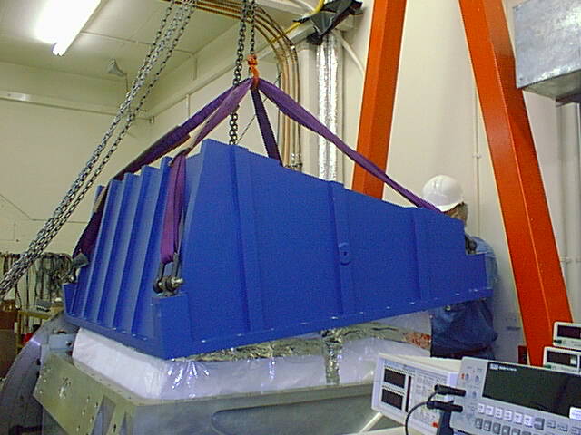
Figure11.8. Installing the front
cover of the cryostat (UKIRT configuration).
|
| Comments: | Done
by: | |
| Checked
by: | |
|
| 11.9 Tighten
the bolts (M12 * 45 long) holding the section of the vacuum
vessel onto the centre section. The cryostat will
need to be rotated to access those nearest the manipulator. |
| Comments: | Done
by: | |
| Checked
by: | |
|
| Remove the Window
Assembly from it's dessicated storage. Remove the external cover
to fit the assembly to the Vacuum cover. Then replace the cover
to keep the window dry. This should be done
only when the cryostat is ready for pump. |
| Comments: | Done
by: | |
| Checked
by: | |
|
| DATE/TIME: |
| 12.1 Position
the cryostat so that the grating drum can be lowered from above
at the top with the interface between the grating drum and the
centre section horizontal. |
| Comments: | Done
by: | |
| Checked
by: | |
|
| 12.2 |
| Comments: | Done
by: | |
| Checked
by: | |
|
| 12.3 Remove
the protective plastic film covers from the stepper motors. |
| Comments: | Done
by: | |
| Checked
by: | |
|
| 12.4 If
it has been stored with the main drum bearing vertical, the
grating drum can be rotated using two hoists and slings as shown
in Figure 11.4. The purple coloured sling is use to lower the
drum into the cryostat, and it should have two, equal length
brothers.
Figure 12.4. Rotating the grating
drum.
|
| Comments: | Done
by: | |
| Checked
by: | |
|
| 12.5 If
absent, fit five grey coloured bar shaped snubbers to the centre
section radiation shield to act as guides when inserting the
drum). |
| Comments: | Done
by: | |
| Checked
by: | |
|
| 12.6 Fit
two lifting shackles (the third is not required) to the grating
drum on the side nearest to the motors and lift into position
over the cryostat opening. First remove the perspex cover from
the Grating Assembly and then the perspex cover from the open
face of the centre section where it protects the spectrometer
collimator and camera optics. Lower the Grating Exchange Assembly
into the centre section as shown in Figure 11.6, (drum mass
126kg). Three spring fingers push the assembly
into a three point mount in the last 20mm of wave.
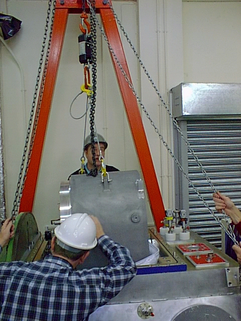
Figure 12.6. Lowering the grating
drum onto the main optical bench.
|
| Comments: | Done
by: | |
| Checked
by: | |
|
| 12.7 Tighten
the captive bolts holding the grating drum to the centre section
to a torque of 67Nm using the special
tools provided (two Allen key ended bars 57cm and 67cm long).
Remember to replace the access hole covers after use. |
| Comments: | Done
by: | |
| Checked
by: | |
|
| 12.8 Plug
in the two motor cables and one status cable running from the
centre section to the grating drum. Note that the tag screw
is absent from the cover of the wavelength drive motor since
it would foul the radiation shield. |
| Comments: | Done
by: | |
| Checked
by: | |
|
| 12.9 Connect
the two thermal wicks between the motors of the grating drum
and the Radiation Shield
The wick attached to the motor which rotates the drum is tricky
to access (see Figure 12.9).
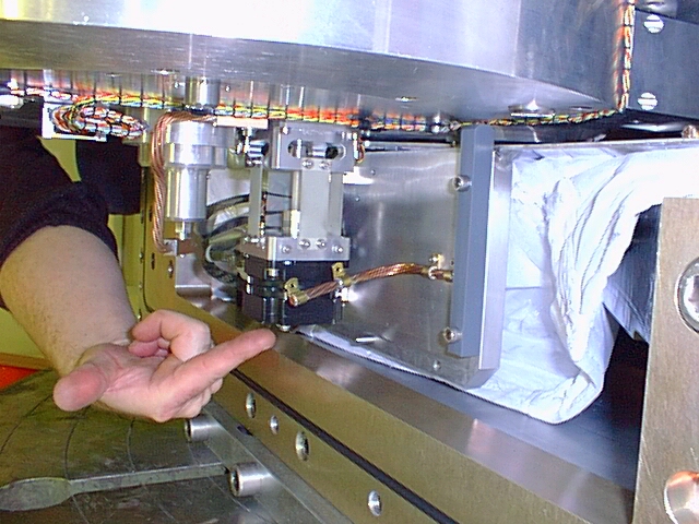
Figure 12.9 The thermal wicks on
the grating drive motors. The hand is pointing to the wavelength
drive wick at the left (note the grey snubber bar on the radiation
shield). The right hand picture shows the difficult to access
grating exchange motor wick.
|
| Comments: | Done
by: | |
| Checked
by: | |
|
Grating Assembly Mechanism Check
Before closing the grating vacuum cover the system should
be connected to the Cryostat Control system to confirm the
performance of the Grating mechanism and status switches.
The connection to the Grating temperature sensor should also
be checked. (A complete status switch check can be performed
using the Status cable break-out box if desired). Before driving
the motors remove all perspex films used to cover the motor
shafts.
|
| The test of the mechanisms
is probably best performed as a series of "forced datums"
selecting each grating in turn. The status switches should be
observed throughout to check for operation. |
Drive
|
Echelle
|
Med N1
|
Med N2
|
Low Q
|
Low N
|
| Round 1 |
|
|
|
|
|
| Round 2 |
|
|
|
|
|
Grating Assembly Status Switches
Status Switch set
|
1
|
2
|
3
|
4
|
| Wavelength Datum |
|
|
NA |
NA |
| Grating Datum (spatial datuming) |
|
|
NA |
NA |
| Wavesafe (can wavelength be selected) |
|
|
NA |
NA |
| Drumsafe (can drum be rotated) |
|
|
NA |
NA |
| Gratcode (to identify the grating) |
|
|
|
|
| Comments: | Done
by: | |
| Checked
by: | |
|
Grating Assembly Temperature Sensor Check
Indicate temperature reading either directly from scanner
or from CCS
Temperature Monitor A
|
Temp (K)
|
Temperature Monitor B
|
Temp (K)
|
| 1 Rad Shield Nitrogen Can |
NA
|
1 JT Stage 1 |
NA
|
| 2 GM Stage 1 |
NA
|
2 JT Stage 2 |
NA
|
| 3 Rad Shield Grating Cover |
NA
|
3 JT Stage 3 |
NA
|
| 4 GM Stage 2 |
NA
|
Unused |
|
| 5 Rad Shield Front |
NA
|
Unused |
|
| 6 Grating Assembly |
|
6 Filter Wheel Motor |
NA
|
| 7 Slit/Field Rotator housing |
NA
|
Unused |
|
| 8 Imager Stop |
NA
|
Unused |
|
| Comments: | Done
by: | |
| Checked
by: | |
|
| 12.10 Remove
the five grey snubber bars. |
| Comments: | Done
by: | |
| Checked
by: | |
|
| 12.11 Manually
lower the Grating end Radiation Shield cover into position.
Ensure that the small side cover has been fitted (removal no
longer required). Tighten the bolts connecting the grating radiation
shield to the centre section radiation shield (torque should
be 14.7 Nm). |
| Comments: | Done
by: | |
| Checked
by: | |
|
| 12.12 Install
the multi-layer insulating blanket over the grating drum radiation
shield, securing the joint with the velcro pads. |
| Comments: | Done
by: | |
| Checked
by: | |
|
| 12.13 Mount
eye-bolts in the grating drum cover and lower it (mass = 100kg),
onto the centre section of the vacuum vessel. (Note that it
is easy to lower into position 180 deg out)
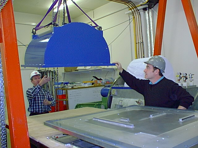
Figure 12.13. Installing the grating
drum vacuum cover.
|
| Comments: | Done
by: | |
| Checked
by: | |
|
| 12.14 Tighten
the bolts connecting the grating drum vacuum cover to the centre
section. |
| Comments: | Done
by: | |
| Checked
by: | |
|