![]()
![]()
![]()

![]()
 H-alpha Filter specifications
Filter substrate Inteferrogram
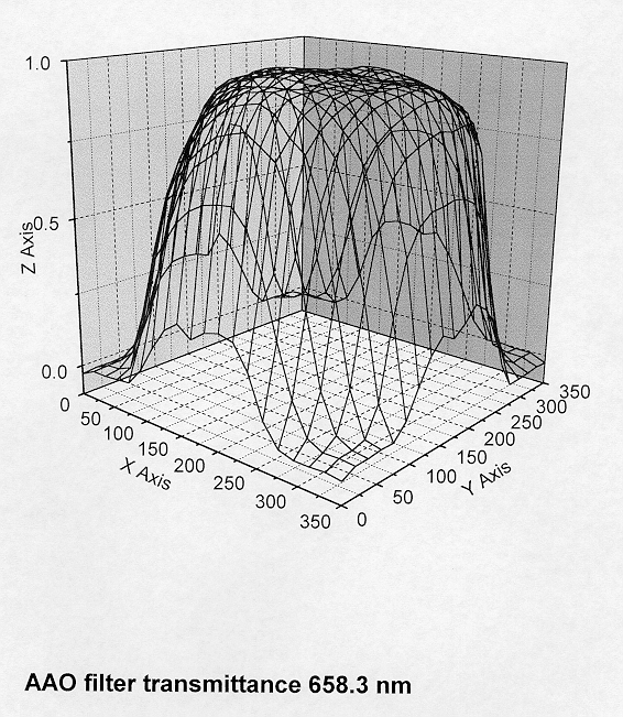
3-D H-alpha Filter transmission profile
H-alpha Filter specifications
Filter substrate Inteferrogram
3-D H-alpha Filter transmission profile
![]()
Basic design
3-cavity design, ion-assisted deposition (IAD) of refractory oxide material on both sides of a SCHOTT RG610 R-type band filter.
Filter size
Size: 360x360mm = 14x14inches
Probably the wolrds largest single element `monolithic' H-alpha interference filter.
Clear Aperture (CA)
11.5inches (292.1mm) diameter minimum.
Filter thickness
Measured thickness: 5.53mm.
FWHM of filter bandpass
FWHM: 70+/-5Å (4.6Å maximum variation acheived in practice over 11.5inches)
Central Wavelength (CWL)
CWL: 6590+/-25Å
The CWL variations incorporate the affects of the F/2.48 beam.
Blocking
Blocking: 0.01% of peak out of band transmission over the range 2000Å-6990Å.
Transmitted wavefront
Transmitted wavefront: Lambda/4 or better.
Peak Transmission
Peak: >85% across most of CA with 5% max variations. Transmission drops to
about 70% by 5.75inches from centre
Temperature effects
Quoted CWL temperature shift: 0.035Å per degree C.
For an extreme operating range of -5deg.C to 30deg.C (highly unlikely at the
UKST) this only corresponds to a blueward shift of 1.23Å.
Coating refractive index
1.973.
Surface quality
S/D (scratch/dig)= 80/50. Basically minimise scratch/dig as much as possible.
Humidity tolerance
The provided filter will meet or exceed the
military standard for protection against humidity.
Polarisation effects for off-axis rays
At large incident angles the filter peak will broaden and split into two
peaks whose polarisations are 90degrees apart.
Plots provided by Barr reveal that with 10.64degrees
AOI in collimated light the s- and p-planes of polarization have bandpass
shifts of only 1.8Å wrt each other.
Physical filter deformation
The filter is likely to be quite heavy such that physical deformation of the
filter under gravity might be expected at some level. When in the telescope the
filter will sag under its own weight in the same sense as the existing curvature
of the mandrel. Barr have not given any
figures but `think' that any minor sagging will not create any problems.
Focus shifts
Introducing a filter of thickness 5.5mm with an assumed
average r.i. of ~1.6 will cause a focus shift of 2.06mm - well within the
capabilities of the UKST focus range.
Cleaning
The filters surfaces can be easily cleaned with a lint
free soft cloth soaked in methanol, acetone or ethanol. The coatings also
meet or exceed military standards for moderate abrasion resistance.
![]()
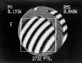
It confirms that the transmitted wavefront (TWF) is better than 1/4 wave per inch.
The interference lines are very parallel with no distortion.
Scanning was with a 2inch aperture and a Helium-Neon laser at 633nm.
Results are integrations of 2732 points from across the entire filter surface.
Peak to Valley range: 0.193 waves (an indication of flatness - TWF variation)
RMS: 0.040 waves (an indication of surface roughness).
![]()
![]()
![]()