 |
|
||||||||||||
| WFCAM Home > Technical > Optical Design Index> Optical Design | |||
UKIRT WFCAM - Optical DesignOptical System Design Description(WFCAM Doc Number 3.1d020O, by David Henry - June 2002)
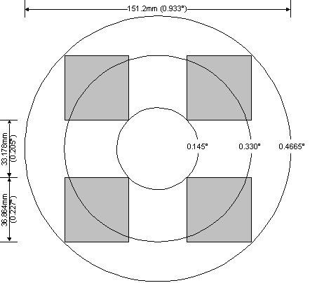
1. IntroductionThis document describes the design of the optical system of the Wide Field Camera (WFCAM) for the UK Infrared Telescope (UKIRT). This document contains the following: · A detailed description of the optical system · The performance of the optical system, in various formats · The detailed prescription of the optical system The optical design of WFCAM is carried out using the Zemax optical design programme. This document is based on design version WFCAM NEW 107.ZMX. 2. Optical System2.1 General IntroductionWFCAM is a wide field imaging camera, primarily designed to carry out large scale semi-automatic surveys of the sky. It operates in the near IR (1-2.5mm). It uses 4 2048x2048 pixel focal plane arrays. These are arranged in a 2x2 pattern, spaced by approximately 90% of a detector spacing. Four separate stepped exposures are taken and combined to produce a single image frame, covering approximately 0.9° x 0.9°. Figure 1 shows the layout of the focal plane, together with the angular field coverage of the optical system.
Figure 1 WFCAM Focal Plane Layout In order to maximise survey speed a pixel scale of 0.4 arcsec/pixel (22.22 arcsec/mm, 18mm pixel) has been chosen. This gives a large field of view of 0.933° diameter. The optical system has been designed for a field of view of 0.94° diameter, giving a small margin over the required field of view. The optical design has a re-imaged pupil where a cold stop is located. This stop minimises the thermal background to ensure maximum sensitivity in the K band, and helps to control stray light. WFCAM has a number of interchangeable filters. The majority of the scientific goals for the instrument will be fulfilled using Y, J, H and K broadband filters. In addition, narrow band filters within this region may also be used. The optical system has been optimised to give maximum performance in the four broadbands. The wavelengths used in the design for each of these wavebands are shown in Table 1 .
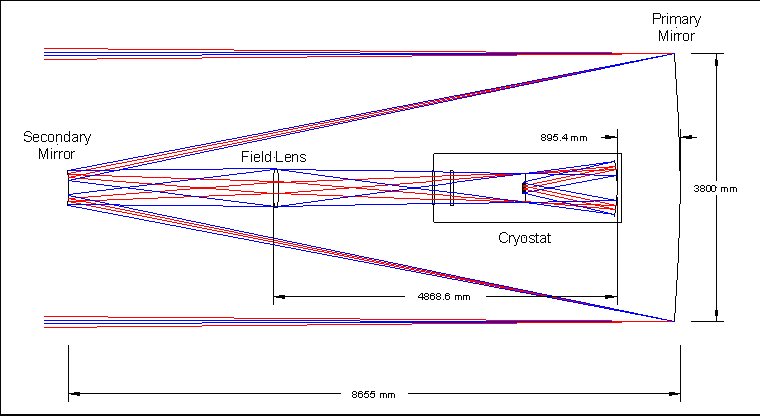
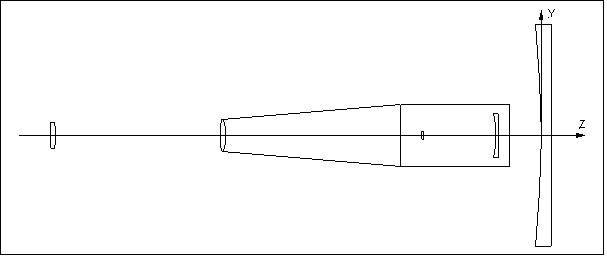
Table 1 - Wavebands 2.2 Description of the optical systemFigure 2 shows an optical layout of the WFCAM optical system. Figure 3 and Figure 4 show close-ups of the cryostat optics and detector optics respectively.
Figure 2 WFCAM Optical Layout
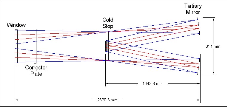
Figure 3 Cryostat Optical Layout
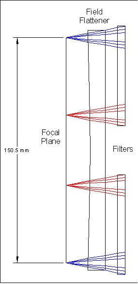
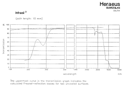
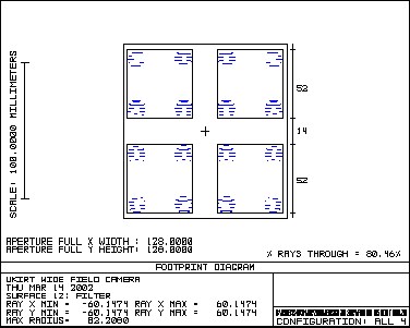
Figure 4 Detector Optical Layout WFCAM uses the existing UKIRT primary mirror. This forms the aperture stop for the optical system. The following parameters for the primary mirror are assumed (see AD1). · Diameter 3802.5mm · Focal length 9516mm · Conic constant -1 To achieve the large required field of view, the WFCAM system uses a new secondary mirror, giving an f/9 intermediate focus at around 5.7 metres in front of the primary mirror. The secondary mirror is mounted on a fast 2-axis precision tip/tilt stage. This is in turn mounted on a HEXAPOD stage, allowing precise movement of the secondary mirror in 6 axes. At the intermediate focus, a large field lens is placed. This forms an image of the entrance pupil (the primary mirror) inside the cryostat. The lens is equi-convex. The next element in the beam is the cryostat window. This is a plane parallel window. The next optical element is a corrector plate. One side of the plate is flat, and the other side has an aspheric profile. It is similar in shape to a Schmidt plate, but is not placed at a pupil image. It therefore helps to correct off axis image quality (particularly coma) as well as spherical aberration. Inside the cryostat an image of the primary mirror is produced by the field lens. The cold stop is located here. The size and position of the cold stop aperture are optimised for stray light rejection in the K-band. The tertiary mirror is located at the rear of the cryostat. This converts the f/9 beam from the secondary mirror into the f/2.44 beam required to give the correct pixel scale. The tertiary mirror is a concave ellipsoid. The beam then passes through the filters. Four separate filters are used, one for each detector array. These are mounted in a mechanism which allows them to be placed in the beam. Each filter is plane parallel. A filter exchange mechanism selects the appropriate filter for use, with the unused filters being stored out of the beam at the side of the cryostat. The filters are discussed in more detail below. Directly in front of the focal plane is a plano-concave fused silica field flattening lens. The full optical prescription of the system is given in section 4. 2.3 Optical MaterialsAll refractive elements in the system are fabricated from Heraeus INFRASIL 302, an infrared grade fused silica. Figure 5 shows the typical transmission of this material. IR grade fused silica gives excellent transmission at the wavelengths of interest, together with extremely high refractive index uniformity. This is an important consideration bearing in mind the large size of some of the components. Figure 5 Transmission of Heraeus Infrasil 2.4 Obscurations in the Optical SystemThe optical design chosen for WFCAM mounts the detector arrays in the incoming beam. These therefore cause an obstruction in the beam, leading to loss of image quality and throughput. For the purposes of calculating the baseline performance of the optical system, the following obscurations are included in the optical system. · A circular hole (1m diameter) in the primary mirror · A square obscuration (142mm x 142mm) located at the position of the filters, between the cold stop and the tertiary mirror. This models the effect on the beam of the obstruction caused by the filters and focal plane unit. 2.5 FiltersThe plot below shows the beam footprint on the front surface of the filters (in J band). A beam is shown coming from the corner of each detector, giving 16 beams in all.
Figure 6 Filter footprints From this we can see that there is no overlap between the beams from each separate detector. This allows the use of separate smaller filters for each detector. The required beam size for each filter is 52mm. 3. Optical System Performance3.1 Focal Length/Pixel ScaleTable 2 gives the focal length and pixel scale of the optical system at the centre wavelength of each waveband. Pixel scale is calculated assuming an 18mm square pixel.
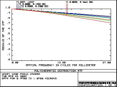
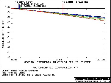
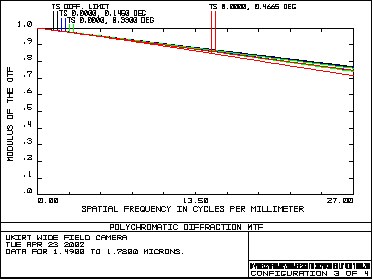
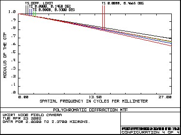
Table 2 Focal length and pixel scale 3.2 MTFFigure 7 shows the diffraction MTF of the system up to a spatial frequency of 27 cycles/mm, in each of the wavebands. The specification frequency for the MTF is at 1.2 cycles/arcsec (26.67 cycles/mm). MTF - Y Band MTF - J Band
MTF - H Band MTF - K Band
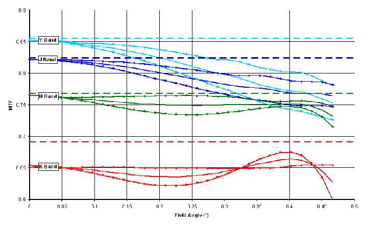
Figure 7 MTF in Y,J, H and K bands Figure 8 shows the variation of MTF (at 27 cycles/mm) with field angle in each of the four wavebands. For each waveband, the plot shows the sagittal (diamond), tangential (square) and average (solid) MTF. The dashed line indicates the (on axis) diffraction limit for each waveband.
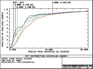
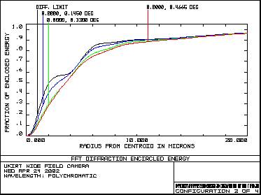
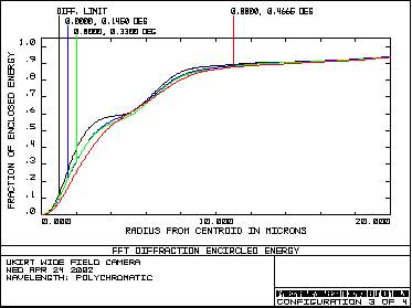
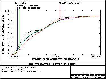
Figure 8 Variation of MTF with field angle 3.3 Encircled EnergyFigure 9 shows encircled energy radius plots for each of the four main wavebands. Encircled Energy - Y Band Encircled Energy - J Band
Encircled Energy - H Band Encircled Energy - K Band
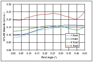
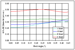
Figure 9 Encircled energy in Y,J,H and K bands Figure 10 shows the 50% and 80% encircled energy diameter (in arcsec) as a function of field angle for each of the four main wavebands.
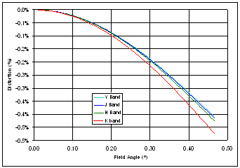
Figure 10 Variation of encircled energy diameter with field angle 3.4 DistortionFigure 11 shows the percentage optical distortion as a function of field angle at the central wavelength of each of the four main wavebands.
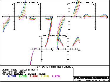
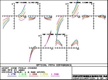
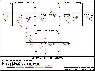
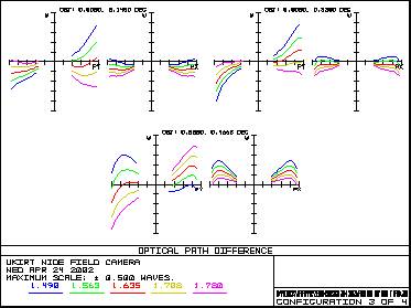
Figure 11 Variation of distortion with field angle 3.5 Wavefront ErrorFigure 12 shows the OPD performance of the system in the four main wavebands. OPD - Y Band OPD - J Band
OPD - H Band OPD - K Band
Figure 12 Wavefront error in Y,J,H and K bands 4. Optical Prescription4.1 Optical Coordinate SystemThe coordinate system used is shown in Figure 13.
Figure 13 WFCAM Coordinate System The origin of the coordinate system is at the pole of the primary mirror, and the optical axis of the system lies along the Z-axis. Light travelling from the sky towards the primary mirror is travelling along the positive Z-axis. All dimensions are in mm. 4.2 Baseline optical prescriptionThe baseline optical prescription is given in Table 3 .
Table 3 WFCAM Optical Prescription Notes: 1) All dimensions and parameters are at the nominal operating temperature. 2) Global positions indicate the location of the pole of the surface along the Z axis. 4.3 Clear apertures and component diametersThe beam diameter, clear aperture diameter and outside diameter for each element is shown in Table 4
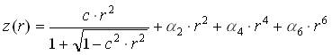
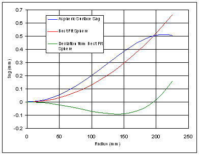
Table 4 Optical element diameters Notes: 1) The beam diameter is the size of the nominal optical beam on the surface 2) The clear aperture is the minimum optical aperture required, allowing for tolerance buildup, flexure, etc. 3) The outside diameter is the physical size of the component, allowing for mounting. 4) Size of an individual square filter element dimensions are edge lengths 5) Field flattener lens is square dimensions are edge lengths 4.4 Corrector plate surface profileThe front surface of the corrector plate is a high order aspheric surface. The surface sag is described by the following equation: z(r) surface sag at radial coordinate r c surface curvature, c=1/radius of curvature a2,a4,a6 aspheric coefficients Table 5 gives the coefficients of this surface at the nominal operating temperature of 250K.
Table 5 Corrector plate aspheric coefficients (250K) Figure 14 shows the profile of the surface sag, together with the deviation of the aspheric profile from the best fit sphere.
Figure 14 Corrector plate aspheric profile Table 6 shows a table of the sag values against radius (at 250K).
Table 6 Aspheric Profile Sag 4.5 RefocussingTo achieve optimum performance, the optical system requires refocussing of the secondary mirror and detector for each of the four main wavebands. This is achieved using the secondary mirror collimation unit and the detector focus mechanism. The main driver behind the incorporation of a detector focus mechanism comes from the thermal design of the cryostat. As the thermal model only predicts component temperatures to an accuracy of a few Kelvin, it is difficult to design the optical system such that it will be in focus at the operational temperature. Small errors in the predicted temperature lead mainly to focus errors, which are easily corrected with a focus mechanism. The incorporation of a detector focus mechanism also allows the use of curvature sensing techniques. The focus mechanism moves the entire detector assembly, including the field flattening lens. The optical effect is therefore a variation of the distance between the filter surface and the field flattener. Table 7 shows the position changes for the secondary mirror and the detector focus mechanism.
Table 7 Nominal secondary mirror and focus mechanism positions Notes: 1) Offsets are measured from the nominal positions listed in Table 3 . 2) Positive offset is away from primary mirror, negative is towards 3) Detector focus global position refers to the pole of the front surface of the field flattener 4.6 Thermal effectsThere are two thermal effects which have an effect on the optical design; the change in refractive index with temperature, and the change in dimension with temperature. The nominal temperatures of each optical component are shown in Table 8
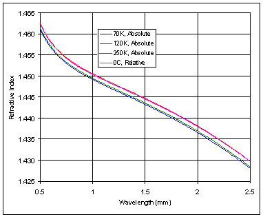
Table 8 Nominal operational temperatures 4.6.1 Refractive index thermal variationAll of the refractive elements in WFCAM are of infrared grade fused silica (Heraeus Infrasil 302). Refractive index thermal variation is accounted for by using different glass models to represent different temperatures. Data for the room temperature (293K) refractive index is taken from the Heraeus product catalogue. For calculation of the refractive index at other temperatures, the room temperature data is scaled in accordance with calculations in Matsuoka [1] and Wray & Neu [2] . Figure 15 shows the refractive index vs. wavelength for the Infrasil glass models at the four temperatures used in the WFCAM design.
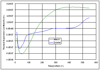
Figure 15 Infrasil refractive index The models for 70K, 120K and 250K represent the absolute refractive index (in vacuum) as they are used for lenses inside the cryostat. The model for 0°C represents the relative refractive index (in air), as it is used for elements outside the cryostat. 4.6.2 Dimensional thermal variationThe WFCAM optical system as designed is at nominal operating temperatures, but all components are made and tested at room temperature. Dimension changes with temperature are assessed by applying a thermal expansion scaling to the operating temperature dimensions. Data for the thermal expansion coefficient of Zerodur and Infrasil are taken from Englisch [3] . Figure 16 shows the variation of thermal expansion coefficient with temperature.
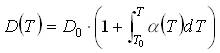
Figure 16 Thermal expansion coefficient Dimensional changes are then given by:
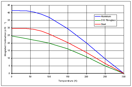
where D0 = dimension at operational temperature T0. Table 9 shows the change in dimensions with temperature. Table 9 Dimension changes with temperature With the exception of the corrector plate aspheric surface, all of these changes are well within the tolerances specified on the parameters (see AD2). Therefore, the values specified on the component drawings are those of the nominal design at the operational temperatures. As the corrector plate aspheric profile is a nominal shape and is not toleranced directly, the room temperature values for the radius and the aspheric coefficients are specified on the corrector plate drawing. 4.6.3 Global PositionsThe change from room (laboratory) temperature to operational temperature changes the global position of the optical elements. A simple model is used to estimate these changes, based on the materials used in the instrument construction. The model calculates the global positions of the optics at 20°C, and can then be cross checked against more accurate thermal models. Data for the thermal contraction of the materials used in the instrument is taken from the ATC materials database. Figure 17 shows the integrated thermal contraction of the three main materials used (Aluminium, Steel and G10 fibreglass).
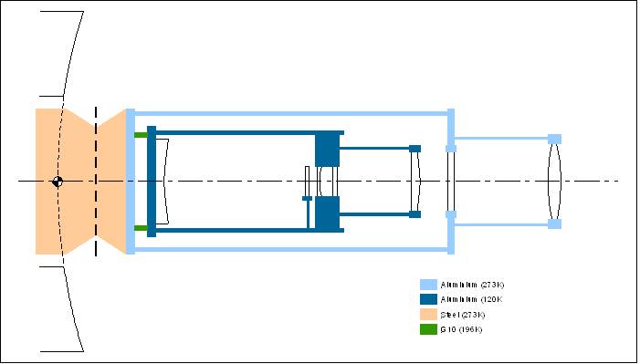
Figure 17 Integrated thermal contraction of materials Figure 18 shows the simple thermal model used to calculate the changes in global positions. For each components, the change in distance for the surface vertex closest to the tertiary mirror is calculated. Changes in optical component thickness with temperature are ignored. All positions are measured relative to the pole of the primary mirror.
Figure 18 Simplified Thermal Model Table 10 shows the estimated global positions at 20° C.
Table 10 Global positions at 20°C [1] Temperature dependence of refractive index of SiO2 glass, Matsuoka, Kitamura, Fujinaga, Yamashita, Journal of non-crystalline solids, Vol 135, 1991 [2] Refractive index of several glasses as a function of temperature and wavelength, Wray, Neu, JOSA, Vol 59, No 6, 1969 [3] Quartzglass for space optical applications, Englicsh, Proc. SPIE Vol 1118 (1989)
|
||||||||||||||||||||||||||||||||||||||||||||||||||||||||||||||||||||||||||||||||||||||||||||||||||||||||||||||||||||||||||||||||||||||||||||||||||||||||||||||||||||||||||||||||||||||||||||||||||||||||||||||||||||||||||||||||||||||||||||||||||||||||||||||||||||||||||||||||||||||||||||||||||||||||||||||||||||||||||||||||||||||||||||||||||||||||||||||||||||||||||||||||||||||||||||||||||||||||||||||||||||||
| Last updated on Wednesday, 11 February, 2004 3:17 PM |