|

|
It is vital that the
slit manifest matches the slits actually loaded in the wheel.
Be sure to update this page whenever new slits are installed. |
| Comments: | Done
by: | |
| Checked
by: | |
|
|

|
The slit positions are defined in the following table,
which represents the slit wheel as viewed from the field rotator
side, as shown in Figure 1.
|
|
|
Remember to update the slit manifestat the
same time as installing new slits in the wheel. |
| |
| Slits installed 5rd March
1999 |
| Pinhole mask |
CLEAR (normally 16 pixel) |
8 pixel |
| 1 pixel |
|
6 pixel |
| 2 pixel |
3 pixel |
4 pixel |
|
Figure 1. The slit wheel viewed from
the field rotator side. The 16 pixel slit is shown at the
top, with the copper coloured pinhole mask to its left.
|
| To separate the field rotator from the Slit
Wheel, first remove the field rotator motor (by undoing the
four screws which hold the it to the common base plate) and
the datum switch micro-D connector. |
| Undo the three screws holding the field rotator
to the common base plate and remove it, being sure to protect
the newly exposed inner surface of the field rotator optics. |
| Undo the two screws which secure the black
slit mask to the rotatable slit mount. |
| Carefully remove the blackened slit mask and
the delicate copper slit using tweezers (see Figure 2). Avoid
contact with the slit itself; use the screw holes to get a grip. |
|
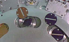
Figure 2. The copper slit and blackened
slit mask (for the 16 pixel slit) being removed from the slit
wheel. Update the slit manifest.
|
| Comments: | Done
by: | |
| Checked
by: | |
|
|
|
|
|
|
|
|
|
|
|