|
|
| It takes two people and a crane (the drum weighs
134 kg) to remove the diffraction gratings. |
| The gratings are both delicate and valuable.
Gloves and face masks should be worn, and as soon as they have
been removed the gratings should be stored in a safe place. |
| Clean all meshing parts with ispropyl alcohol
to remove any potential ice forming materials. |
|
|
|
|
 The
? and accuracy of the Grating Drum relies on keeping each
group of components together. Marking and numbering
does exist but good working practices in storage? will help
too. The
? and accuracy of the Grating Drum relies on keeping each
group of components together. Marking and numbering
does exist but good working practices in storage? will help
too.
IMORTANT
Turn grating drum to a position mid-way between two gratings
and undo the M3 bolt from behind grating. (This only applies
to the NI gratings).
IMORTANT
With the ECHELLE the grating should be in its normal position
but turned through 90 degrees in wavelength to undo the M3
bolt.
Remove balance weights, two per grating, held on with
four M4 screws. This allows access to the bolts and springs
holding the grating to its casting. Take care not
to lose any spacers behind the balance weights.
Attach the grating handle to the correct grating transfer
plate (there are two of these, as shown in Figure 1.
One is for the echelle and the other, labelled 'NI', is for
all other gratings).
|
| |
|
Figure 1. The special diffraction
grating handling tool.
|
|
Mount the handling tool to the grating support
casting by the four screws at its corners. The casting will
be left in place in the drum once the grating has been removed.
|
|
Insert and finger tighten the two jacking screws (spec.)
in the holes in the handling tool. These will be used to jack
the grating out of its carrier.
|
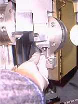
|
Progressively undo the four flexure fixing screws through
the access holes on either side of the jacking screws, at
the same time as tightening the jacking screws. The grating
should be seen to move towards the handling tool, with assembly
appearing as shown in Figure 2.
|
|
Figure 2. The LOW-N grating with
the handling tool in place, ready to begin jacking.
|
|
Carefully loosen the screws mounting the tool to the grating
support casting and then remove the lower pair.
| Comments: | Done
by: | |
| Checked
by: | |
|
|
With one person supporting the grating using the handle,
the other person should undo the upper two remaining screws
so that the grating with its handle can be removed.
|
|
Take
particular care when removing the echelle from the drum as
it a tight fit, (and the most expensive grating to replace!)
|
|
Remove the handle and install the perspex cover to protect
the ruled surface. Store the grating in a safe place.
|
| Comments: | Done
by: | |
| Checked
by: | |
|
|
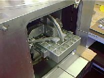
Rotate the grating drum until the desired grating's support
casting is in vogue, as shown in Figure 3. Each drum bay can
be identified with it's particular grating by an engraved
label.
|
|
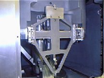
Figure 3. The grating drum positioned
ready to receive the LOW-N grating.
|
|
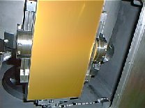
Identify the grating to be installed by the engraved label
on its edge, as shown in Figure 4. When mounted, this label
(and the heiroglyph identifying the grating blaze angle),
should be on the left-hand side of the grating support casting
as pictured in Figure 3. The shim shown to the right of the
grating in Figure 4, (2mm thick for all gratings), will mount
on the fixed flexure on the right hand side of the grating
support casting.
| Comments: | Done
by: | |
| Checked
by: | |
|
| |
|
Figure 4. The LOW-N grating and
it's 2mm shim ready to be mounted in the grating drum.
|
|
The installation procedure is the reverse of the procedure
for removal. First remove the storage cover and mount the
handle.
|
|
Attach the grating to the support casting using the mounting
screws shown in Figure 1 and with the shim in place on the
right hand side of the casting
|
|
Progressively tighten the four flexure fixing screws with
springs through the access holes on either side of the jacking
screws, at the same time as loosening the jacking screws.
The grating should be seen to move towards the grating support
casting, as shown in Figure 2.
|
|
Remove the jacking screws.
|
|
Remove the handle by undoing the four screws at its corners.
|
|
Replace balance weights.
Tighten M3 screws behind all gratings.
| Comments: | Done
by: | |
| Checked
by: | |
|
| Once all of the gratings have been removed,
The ski-jump can be removed. |
| In order to remove the ski jump it is necessary
to undo the screw which connects the thermal wick from the central
drum bearing to the back surface of the ski jump. This can only
be accessed by lifting the drum (mass = 126kg) as shown in Figure
5. The screw is shown to the right in Figure 6, between the
two lines of three holes where the ski jump mounts onto the
conical bearing support structure. |
|
Figure 6. The thermal wick connecting
the ski jump to the grating drum bearing.
|
| Unplug the datum switch cable and remove the
six screws which hold the ski jump into the drum; remove the
ski jump. Note any dust (gold may be the echelle replica or
grating coating, grey may be the vespel worms). |
| Comments: | Done
by: | |
| Checked
by: | |
|
| Refer to brake assembly drawing number 37a84a.
Note that the echelle's assembly is about 2mm shorter than those
for the other four gratings. The parts of the assembly are shown
in Figure 7. |
|
Figure 7. The component parts of
the grating brake assembly. The red graphic shows the order
and orientation of the six disk springs (Belleville washers)
when assembled.
|
| Insert the dowel rod through the left brake
arm and the right brake arm, and mount the rod cap, washers
and fixing screw in the order shown in Figure 7.. |
| Mount the brake assembly loosely in the grating
drum, press the vespel brake pads onto the wavelength drive
gear to square them up and then tighten the eight screws which
hold the assembly onto the central shaft of the drum. (see Figure
8). |
|
Figure 8. The installed brake assembly
on the grating wavelength drive.
|
| Tighten the fixing screw until the disk springs
are flattened and then back off by 1/8th of a turn. The resultant
braking force on the grating should then be 1.0 to 1.5kg. |
| Comments: | Done
by: | |
| Checked
by: | |
|
| When removing the wavelength drive selection ring
be sure that the stopwork mechanism for the echelle's wavelength
drive is positioned so that its lever arm does not foul the
drum casting, as shown in Figure 8. |
|
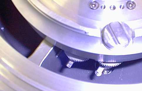
Figure 9. The echelle stopwork mechanism
positioned correctly for removal of the wavelength drive selection
ring.
|
| Comments: | Done
by: | |
| Checked
by: | |
|
| The wavelength drive motor is mounted as shown
in Figure 10. The carousel must be hand cranked until the Oldham
coupling can be inserted and connected in the correct orientation.
A spacer under the motor mounting bracket sets the coupling's
clearance in the along-shaft direction. |
|
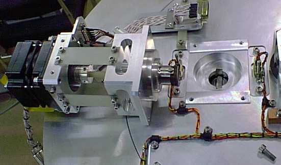
Figure 10. The wavelength drive motor.
|
| Comments: | Done
by: | |
| Checked
by: | |
|
| With the grating support castings and their
wavelength drive mechanisms already assembled in the grating
drum, the lower stub shaft (shown in Figure 11) can be positioned
on the two dowels in the drum and then secured in place using
the eight screws. |
|
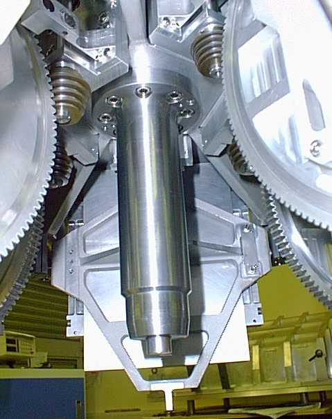
Figure 11. The lower stub shaft mounted onto the
grating drum.
|
| Lower the long, heat conducting copper shaft
into the lower stub shaft and then mount the upper stub shaft
using its eight screws. The upper stub shaft is shown in Figure
12 protruding from the stopwork and wavelength drive assembly.
|
|
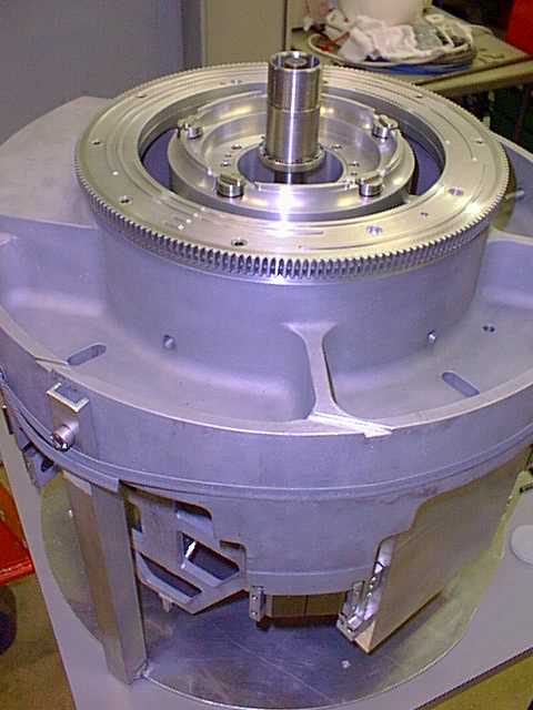
Figure 12. The grating drum casting with the central
shaft inserted and the stopwork and wavelength drive guide
mechanism mounted. Note the drum support bracket. A grating
blank is shown mounted in the drum, normally the gratings
should be removed before working on the drum.
|
| Slide the lower element of the upper bearing
onto the shaft (using a cylindrical tool to avoid separating
the bearing), and seat it on the flange in the shaft, as shown
in Figure 12. The two marks on the bearing rim should be on
the visible, top surface. |
| Loosely mount the worm drive gear (already
assembled in its mount, as shown in Figure 13) on the inner
surface of the top hat shaped carousel lid using the two screws.
The worm gear will be tightened when it is fitted to the gear
on the main part of the drum later. The grating/carousel drive
bracket shown to the right in Figure 13 can be attached to the
lid at this stage, it has a hole in it for access to the locking
screw in the drive shaft. |
|
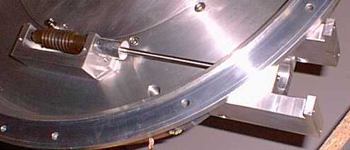
Figure 13. The drum drive worm gear assembly.
|
| Carefully lower the drum lid onto the grating
drum, so that it rests on the upper bearing support collar.
Inspect the mesh of the worm and gear in the drum drive train. |
| Slide the upper element of the upper bearing
set onto the upper stub shaft. The two bearings each have two
marks on their rims which should be facing each other when assembled
(see drawing number XX). |
| Complete the assembly of the upper stub shaft
bearing using the components shown in Figure 14. The spacer
goes on first, with the thin walled recess uppermost to receive
the three Belleville washers, which should be installed with
their concave faces all facing downwards. |
| Screw one of the two threaded rings onto the
shaft and tighten it using the C-spanner to compress the Belleville
washers. Use the other threaded ring to lock it in place. |
|
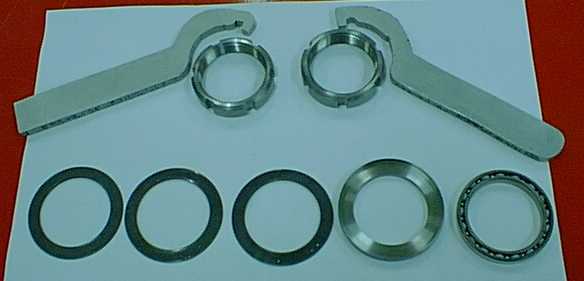
Figure 14. The tools and components for pre-loading
the upper stub shaft.
|
| Mount the top dome with its spring loaded thermal
wick over the end of the upper stub shaft, as shown in Figure
15. |
|
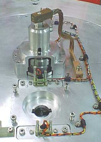
Figure 15. The dome over the upper stub shaft.
|
| The bearing for the lower stub shaft is mounted
in the bell shaped housing in the main grating drum enclosure,
as shown in Figure 16. To align the bearing, the drum should
be lowered into place with the bell housing screws loosened
so the lower bearing can move. |
|
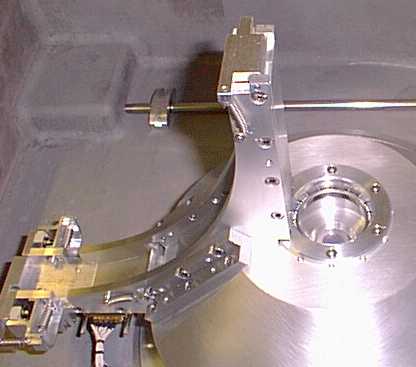
Figure 16. The bell housing in the grating drum
housing, showing the lower stub shaft bearing.
|
| Retighten the bell housing screws. |
| Comments: | Done
by: | |
| Checked
by: | |
|
| If necessary, check that the clutch (shown in
Figure 17) on the carousel drive is set to slip at the correct
torque setting. Then connect the motor and clutch to the drum
drive shaft (and worm gear) by fitting the screw and spring
washer through the access port in the drive mount. This is a
tricky operation. |
|
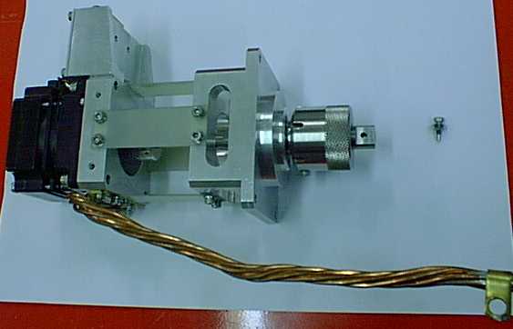
Figure 17. The carousel drive motor with its clutch
mechanism and the screw for attaching the drive shaft.
|
| Comments: | Done
by: | |
| Checked
by: | |
|
|
|
|
|
|
|
|
|
|
|
|
|