| Last updated on 28-Aug-2001 2:11 PM |  |
 |
Focus Translation Assembly Service
1 Assembling the Focus Translation Assembly |
|
|
1 Assembling the Focus Translation Assembly
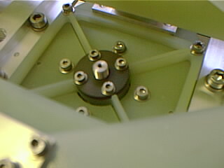
Close cup of lead screw nut.
|
Front view on focus lead screw assembly. Focus flexures are screwed and dowelled in place.
|
||||||
|
Reverse view on above sub-assembly. Note vespel lead screw fixed to G10 cross flexure. |
||||||
|
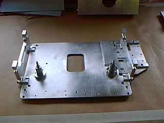
View of focus translation base plate with translation flexure attached. |
||||||
|
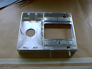
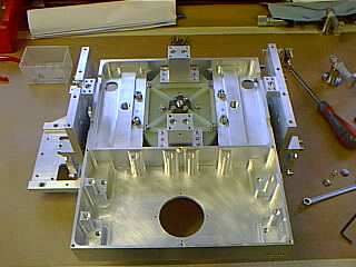
View of unpopulated detector box housing. |
||||||
|
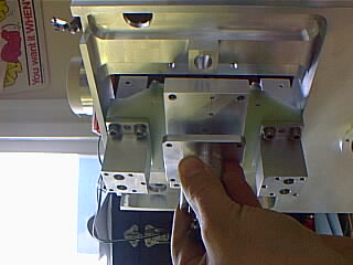
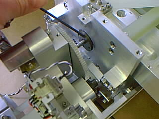
Assembly of focus lead screw assembly into detector box housing. Locate on two dowels and secure with four M6 cap screws. |
||||||
|
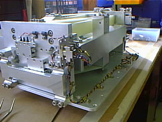
Detector box housing with focus lead screw sub-assembly attached. |
||||||
|
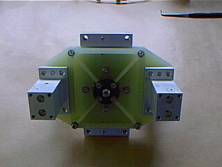
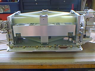
Reverse view of the detector box housing. |
||||||
|
Fit G10 brace as shown with end cut outs on same side as gear wheel. Secure with four screws. |
||||||
|
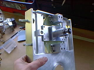
Fit end plates, location is on dowels on cross brace, attach bottom focus flexure with dowels and secure with steel plates. |
||||||
|
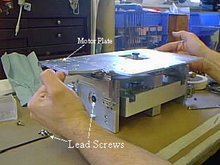
On bottom side, place baseplate in position with motor plate to the lead screw side. |
||||||
|
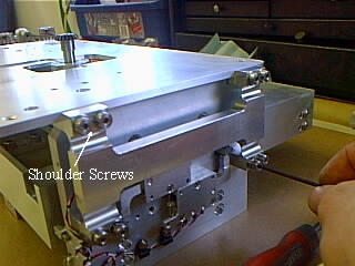
Secure base plate to end plate using sixteen soulder screws. Ensure cutouts on flexures clear switch assemblys. |
||||||
|
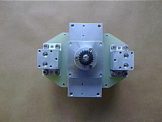
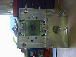
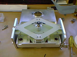
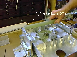
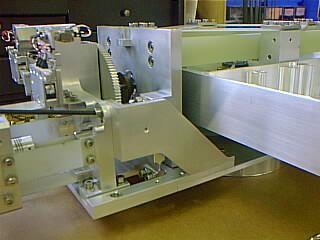
Top view of assembly before fitting top G10 cross bars. |
||||||
|
G10 cross bars being fitted secure to endplates with screws each side. Check floating nuts are positioned correctly. |
||||||
|
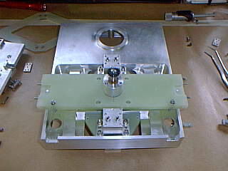
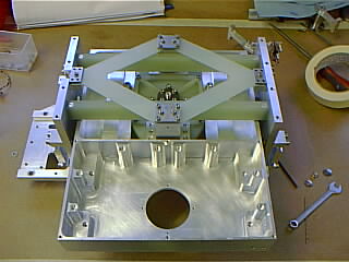
Top view wuith top G10 crossbars in position and top focus flexure in positon and secured. |
||||||
|
Translation motor sub-assembly before installation to base plate. |
||||||
|
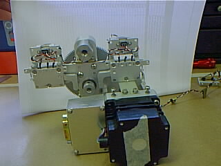
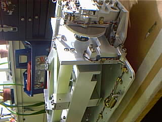
End view showing limit switch mechanisams and actuator. |
||||||
|
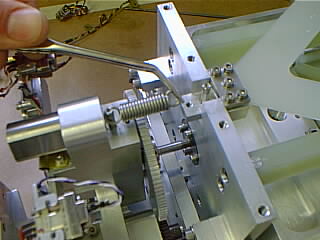
Translation motor assembly being placed in position on base motor plate |
||||||
|
Secure motor assembly to base plate and attach
all screws. |
||||||
|
Offer up vespel translation nut to end plate
ensuring the flexures are in mid position. |
||||||
|
Attach preload springs as shown, at top and bottom. |
||||||
|
Secure wiring in position with p-clips, ensure no cables can be snagged by moving mechanism. |
||||||
|
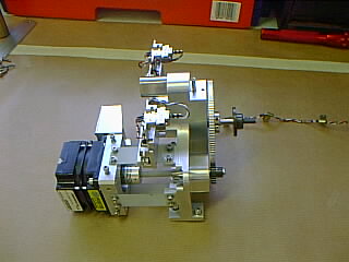
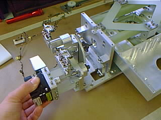
Side view on complete mechanism. |
||||||
|
Wiring routes. |