1 Mounting on the UKIRT Handling
Trolley
Position the two long Michelle feet assemblies on the trolley
using the semi-circular pads to align with the matching features
on the top face of the trolley. Remove the four cylindrical legs
from the feet and loosely secure to the base of the Cryostat.
With the trolley at lowest elevation to avoid the Cold head
assemblies, drive the trolley and feet under the cryostat and align
with the relevant holes on the legs. Secure at both ends of the
legs
 The leg/feet assemblies can be fitted as a unit but driving
the trolley to avoid damage to the cold-heads may be more difficult)
The leg/feet assemblies can be fitted as a unit but driving
the trolley to avoid damage to the cold-heads may be more difficult)
The
Cryostat assembly will nt fit to the Trolley if the Housing for
the Warm Edict (Array) Electronics are fitted.
|
Fitting feet to trolley
|
Attaching feet and legs to the cryostat
 Note that the legs are now cylindrical over the full length
|
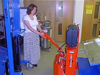
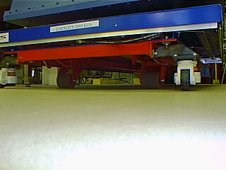
2 Controlling the UKIRT Handling
Trolley
The Trolley has been constructed by fixing a standard 2 ton
Scissors lift to a standard motorised Pallett truck. Subsequent
to delivery and after experience using the equipment at the UKATC
some stabilising wheels were added to the front which are required
when using the scissors lift at high elevation. The primary power
is supplied by battery with hydraulics being used to power the two
lifting elements. Full details of the Handling Trolley controls
can be found in the Suppliers User Manual (link to scanned pdf Document).
Abbreviated information is available below.
Whilst
in theory designed to work on a 1:10 slope this appears to be very
much dependent on surface quality to ensure appropriate grip for
the drive wheel. Thus it is suggested that only LIGHT LOADS (<500kg)
be driven over any sloped surfaces.
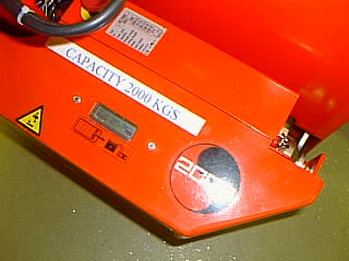
2.1 Drive Controls
A key is used to switch on the power unit. A flat panel display
near the keyswitch is activated when the drive arm is lowered and
indicates battery power level etc. Full details can be obtained
from the Supplier's Maintenance Manual.
|
|
|
| Views showing, at left, the Key (in On position) and LCD Status
Panel, and at right, the Drive Controls - Pallett Lift and horn in
centre and Thumbwheels at side |
|
In order to drive the Unit the Front wheels associated with
the Pallet Truck Element must be fully lowered. This is done with
the UP control in the centre of the Drive column shown above.
|
| The Drive Column must then be lowered until a loud "click"
indicates the engagement of Battery Power. The thumbwheels
either side of the central column can then be used for forward and
reverse control. Rotating the whole column steers
the unit via the rear drive wheel. BRAKING is achieved
either by fully elevating OR fully lowering the drive column. |
|
|
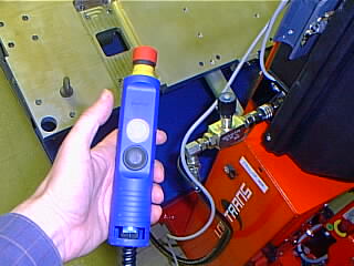
2.2 Lift Control
The Add-on Black box at the Trolley Drive control is the power
source for the Scissors Lift. The controls, shown below, consist
of a valve for controlling the speed of lift OR descent and a simple
two button control for direction of motion. The rate
of lift set by the valve is very much dependent on the load and
so it is generally recommended that the valve be fully shut first
for any fine control operations.
|
|
|
3 Mounting on the Gemini Air-Bearing
Pallet
|
| This operation is usually only performed in the Gemini Telescope
facility although it may also happen during sea-level commissioning
at the Gemini Base Facility. For Gemini Use the Instrument is either
fitted to a side port or the upward looking port. The latter mounting
requires the Instrument assembly to be rotated to sit on its frame.
The cryostat arrives at and leaves the Gemini Dome on the back
of a trailer or Truck and sitting on an appropriate shock isolation
base. The legs and feet used for handling with the UKIRT trolley
are already in place and the Support frame for the Thermal Enclosures
will have been fitted. The Thermal Enclosures are delivered separately
and fitted later.
The operations require access to two crane hoists, one capable
of at least 2000kg and the other a minimum of 1000kg.
|
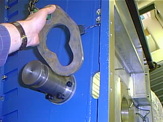
3.1 Side Mounting Orientation
Position the cryostat on its transporter under the Crane. Attach
the lifting lugs to each side of the Gemini Front vacuum cover as
shown. Attach the spreader bar (2500Kg capacity) to the hoist of
larger capacity and then hook the key plates to the Lifting lugs.
|
|
|
|
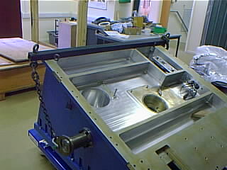
Attach the second hoist to the two lifting eyes at the rear
of the cryostat centre section
|
|
|
|
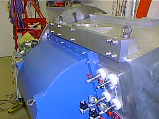
Remove any securing ropes holding Michelle to the transporter
and lift the cryostat so that the feet remain reasonably level.
Position the Air Bearing Pallet under the suspended load in place
of the transporter and lower into place. The G10 semi circles on
the underside of the Feet will position the assembly centrally on
the Pallet.
|
| |