GMOS Project page
The GMOS (Gemini Multi-Object Spectrograph) project at the ATC
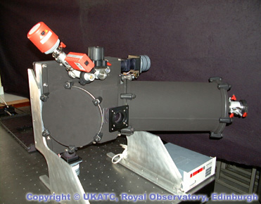
GMOS instrument without enclosure and electronic cabinets
INTRODUCTION
Both Gemini 8-metre telescopes in Hawaii and Chile are now
equipped with multi-object spectrographs (GMOS-North and -South) operating in
the optical region of the spectrum. GMOS-N and -S are versatile instruments
designed to fully exploit the excellent images that the telescopes
produce. They are the workhorse instruments at the Gemini Observatories. GMOS
is an international collaborative project involving the UK Astronomy Technology Centre the Dominion Astrophysical
Observatory of Canada and the University of Durham.
COMMISSIONING
GMOS-South is the latest addition to
Gemini's suite of instruments, following successful commissioning in
2002/03. UK ATC has thus played a key role in 3 of the 4 facility-class
instruments operational at Gemini - GMOS-S, GMOS-N and Michelle.
Commissioning progressed smoothly, with the instrument operating straight
from the box (or from the 24 packing crates it took to transport it!)
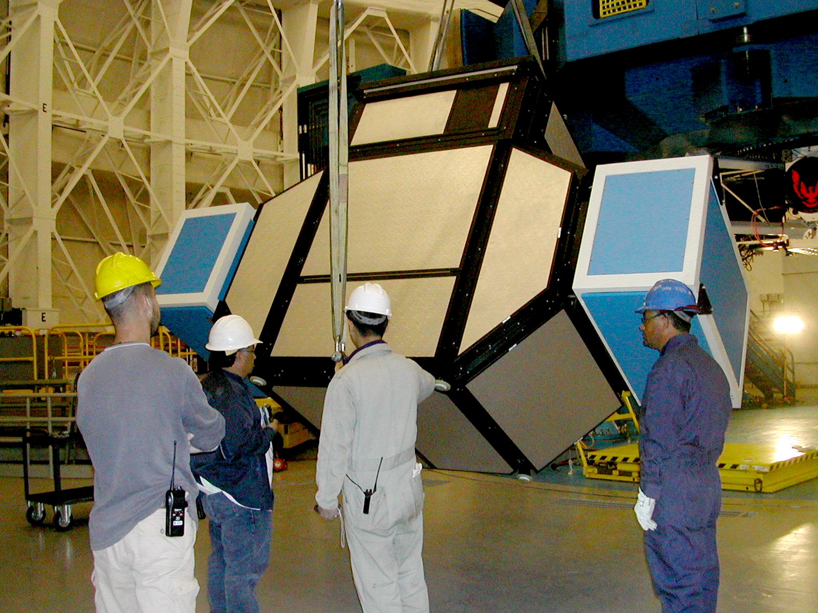
Chris Tierney, GMOS Systems Engineer at UK ATC, oversees
the installation on GMOS-S on the Gemini telescope on Cerro Pachon.
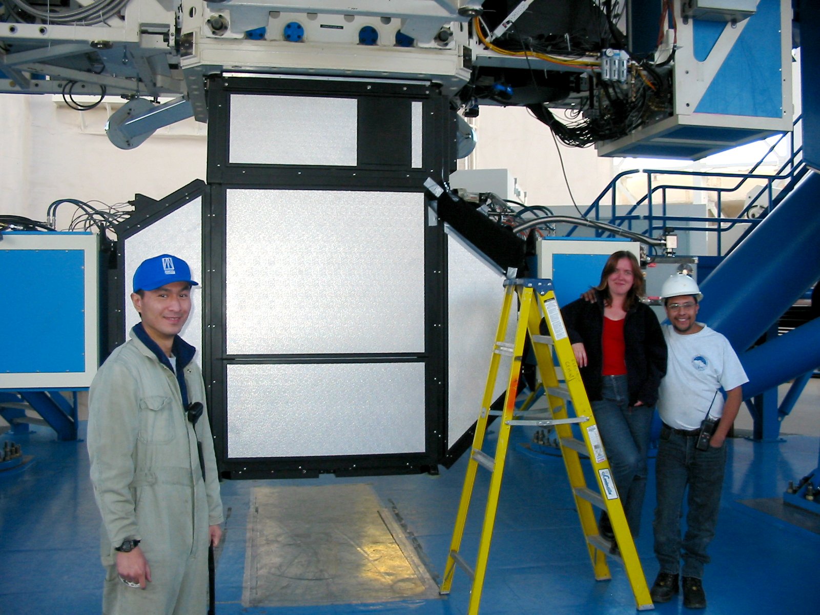
Kei Szeto (DAO, Canada), Morag Hastie (UK ATC) and Luis Godoy (Gemini)
stand proudly beside GMOS-S, successfully mounted on Gemini-South in Chile.
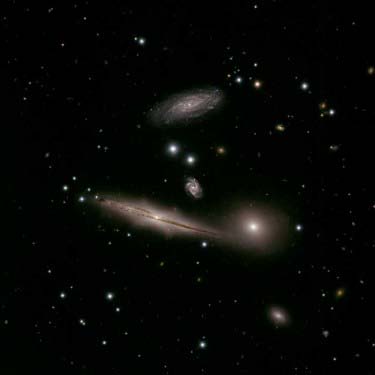
Among the images and spectra acquired during commissioning of
GMOS-S, one image is particularly compelling: this image
reveals remarkable details, previously only seen from space, of
the Hickson Compact Group 87 (HCG87). HCG87 is a diverse group of
galaxies located about 400 million light years away in the direction
of the constellation Capricornus.

Remarkable first-light image, obtained with GMOS-N at the
Gemini-North telescope on Hawaii's Mauna Kea. The image is of the large galaxy
in Pisces called NGC 628 (or Messier 74) has been called the Perfect Spiral
Galaxy due to its nearly ideal form, which is clearly revealed in this image.
MAIN MODES
-
Direct imaging
-
Long-slit spectroscopy
-
Multi-slit spectroscopy using custom-made masks
-
Integral field spectroscopy
BASIC SPECIFICATIONS
| Wavelength range |
0.36-1.1 microns (with a design capability to 1.8 microns) |
| Field of View |
5.5 x 5.5 arcmin |
| Detector |
array of 3 CCDs: each 4608x2048 13.5um pixels |
| Scale |
0.07 arcsec/pixel |
| Filters |
Two wheels with 11 slots + 1 clear aperture each. Initial filter set
is SDSS g' r' i' z'. |
| Gratings |
Grating turret holds 3 interchangeable gratings and one mirror. Initially
6 gratings for 2 GMOSs |
| Resolving power |
R up to 10,000 with 0.25 arcsec slits |
| Slit Masks |
Up to 600 slits per mask, minimum slit width = 0.2 arcsec |
| " |
Straight or curved slits possible |
| " |
Maximum slit length = 5.5 arcmin |
| Integral Field Unit |
0.2 arcsec sampling over 50 square arcsec field |
SCIENTIFIC DRIVERS
Since the GMOS spectrographs are common-user instruments, there are many
scientific drivers, eg:
-
Surveys of faint galaxies which require not only high efficiency but also
the ability to arrange slits in multiple tiers to increase the multiplex
gain.
-
Surveys of dark matter in low mass galactic systems which require the ability
to measure radial velocities to 1 - 2 km/s and multi-object capability
so that complete stellar systems can be surveyed in one observation.
-
Two-dimensional (integral field) spectroscopy of intermediate-redshift
objects on scales similar to that of the Hubble Space Telescope to study
kinematics, star formation and to obtain accurate distance estimates.
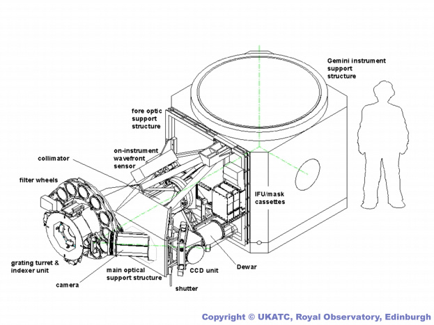
DESCRIPTION OF THE INSTRUMENT
One of the remarkable features of GMOS is the fine image scale, needed
to exploit the excellent images provided by the telescopes. GMOS includes
an integrated on-instrument wavefront sensor to provide the necessary correction
signals for the articulated tip-tilt secondary mirror. Recent observations
with the newly commissioned GMOS-S on Cerro Pachon in Chile achieved natural-seeing
resolution of nearly 0.3 arcsec in the r filter.
OPTICAL DESIGN
The optical design uses refractive optics and reflection gratings. The
image quality is such that 50% of the light is enclosed within a diameter
of ~0.1 arcsec over a field ~7 arcmin in diameter. Sol-Gel very broad-band
anti-reflection coatings are being utilised on the GMOS optics.
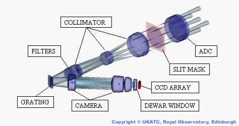
GMOS Optical Path
The optical system includes an integrated atmospheric dispersion compensator
and a corrector to improve the image quality in both imaging and spectroscopic
modes.
Remotely deployable masks are used for both multiple-aperture and single-aperture
spectroscopy. Because of the great accuracy required in the location of
the slits, all masks are designed with the aid of direct images taken with
GMOS. Masks will be made on a facility near to the northern telescope.
With a 5.5 x 5.5 arcmin2 field of view, GMOS should be able to locate hundreds
of objects in a single mask, though typical densities for most projects
are more like 50.
It is possible to make accurate slits as narrow as 0.25 arcsec in order
to exploit the best seeing conditions and to achieve the highest spectral
resolution. The combination of large field, excellent image quality and
the ability to arrange the slits in multiple tiers implies a maximum multiplex
gain of several hundred.
Accurate target acquisition is critical to the instrumental performance.
The simplest and most reliable method is to image the sky through masks
which include small holes through which reference stars can be viewed.
The mask-sky displacement is then used to offset the telescope and rotate
the field to ensure accurate registration.
GMOS provides a large range of dispersion options via a four-position
grating turret which includes a plane mirror for imaging.
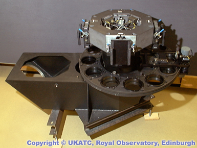
Filter Wheel and Grating Turret
It is a key requirement that the tilt of each grating be maintained
precisely, even when moved out of the light path, so that the spectroscopic
setup is not disturbed during target acquisition. Instrument flexure is
minimised to permit measurement of radial velocities to an accuracy of
1-2 km/s with hourly on-target wavelength calibration. For GMOS-S, based
on Cerro Pachon in Chile where temperature fluctuations can be rapid, a
flexure model incorporating the effects of both temperature and inclination
was derived in the ATC laboratory using a cold room and flexure rig.
MECHANICAL SYSTEM
The mechanical system has been designed to minimise tilts between optical
components so that the only effect of flexure is a slow motion of the image
on the slit of the detector. This means that flexure can be compensated
simply by moving the detector. A novel cryogenic translation and focus
mechanism has been designed for this purpose. The translation mechanism
provides two orthogonal axes of fine motion for the CCD mount. The resolution
of the translation mechanism is 0.4mm per motor step and the total travel
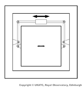
is ±150mm. The principle of operation of a single axis of the translation
mechanism is shown below.
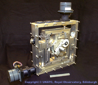
CCD Translation Unit
A central box is supported from a surrounding frame by two pivoted lever
arms. The arms are linked by a cross-piece pivoted to their outer ends.
The levers have a ratio of 5:1. The cross-piece is moved by a leadscrew
and nut, driven by an external stepping motor. The centre of mass of the
box lies on the line joining the two pivots on the box. The centre of mass
of the box plus levers and cross-piece lies on the line joining the two
fulcra on the frame. Meeting these two conditions minimises the twisting
of the pivots due to the changing gravity vector. Backlash in the nut is
removed by using springs (not shown) to pull the cross-piece to one end
of its travel. The second axis of translation is provided by a similar
mechanism which is built as an integral unit around the inner one. The
outer frame of this forms part of the vacuum vessel and carries the attachment
points by which the whole CCD unit is joined to the rest of GMOS.
CCD Assembly
DOCUMENTATION
OTHER LINKS
© UK ATC
Last modified by:
Rob Ivison
12
Sept 2003.